Ground Plane Measurements
by Pat Brown
This articles presents a ground plane measurement technique to optimize the loudspeaker.
The first step to the sound system equalization process is the application of the signal processing required to optimize the loudspeaker. This requires an anechoic measurement of the loudspeaker’s axial response. Some reasons for this important step include:
– To make sure the loudspeaker survived the trip from the factory to the job site
– To assure that the required signal processing (e.g. crossover network, delay) is in place and set properly
– To assess the need for corrective equalization
The axial response is likely the only response curve published by the manufacturer. It’s the only reference response you have for assuring that the loudspeaker is operating properly and at its fullest potential. Sure, there may be additional steps to a system tuning, but this is step one, and omitting it may cast doubt on what you measure and hear further into the system tuning process.
“In Situ” is Often Too Late
Ironically, one of the worst places to perform this measurement is “in situ.” Once the loudspeaker is permanently installed, it’s not easy to get a good look at the direct field. It’s also not easy to make wiring changes or repairs, should they be needed. Reflections from surfaces near the loudspeaker will produce comb filtering over much of the loudspeaker’s pass band. There needs to be a lot of time between the direct field arrival and the first reflection from the environment. While large anechoic chambers, tall mic stands, tall loudspeaker stands come to mind, it can be much easier than that. The ground plane measurement is a time-proven way to get there. All you need is a large space, and outdoors will work on a calm day.
The Ground Plane Measurement
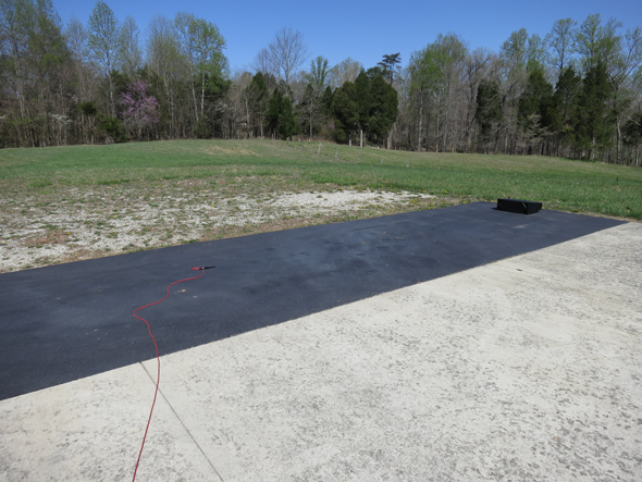
The loudspeaker is placed on the ground plane (GP), and the measurement microphone is placed on-axis and in its far-field. The basic setup is shown in Figure 1. Photos 1 and 2 show my outdoor setup. I can get a 200 ms time window using the placements shown. A motorized turntable can be added to collect polars.
Figure 1 – Side view of a GP measurement setup. The microphone element should be touching the GP for accurate high frequency results.
Photo 1 – My GP “lab” – the great outdoors. The microphone is at 6 m.
Aiming the Loudspeaker
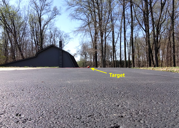
The loudspeaker needs to be aimed at the microphone to get an accurate response at high frequencies. If you’re measuring LF boxes or subs, this is generally not necessary. An angled wood block can provide the tilt. Indoors, a laser will reveal the required angle. The laser may not be visible outdoors, but a handy trick is to use your smartphone camera. Set the camera up for a “selfie” and place it against the grill of the loudspeaker. Adjust the angle until the microphone is centered in the image. You can set a larger object next to the mic to provide a better target. I use an orange lacrosse ball (Photo 2). If the loudspeaker doesn’t have a grill, or has an open mouth, just place a stick across the mouth to place the laser or camera against.
Photo 2 – A smartphone camera, set for a “selfie” can aid in aiming the DUT at the microphone. Some camera apps have a grid or cross-hairs to identify the center of the screen.
Ground Plane vs. Free-Field
Contrary to intuition, the boundary near the loudspeaker has a minimal, essentially negligible effect on the response. This is because the GP measurement puts the floor reflection at the microphone. The sound can’t reflect from the floor twice. The only negative effect is the elimination of the diffraction from the loudspeaker edge touching the floor. This actually makes the response slightly smoother than if the loudspeaker were measured away from the boundary.
The DUT should be either “on” the floor or well away from it (i.e. flown). Placing it a few feet from the floor will produce a loudspeaker > floor > loudspeaker > mic reflection path, and possibly corrupt the low-mid frequency response. The principle is “If you can’t get the mic and loudspeaker away from the boundary, make them part of the boundary.” A GP measurement is essentially a free-field measurement, but with no tall stands required.
On-Site Quality Control
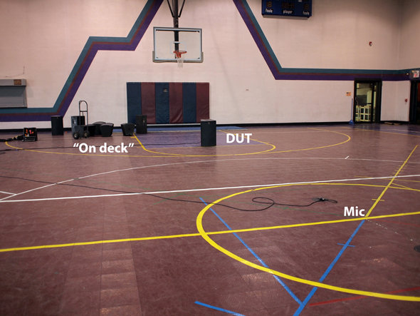
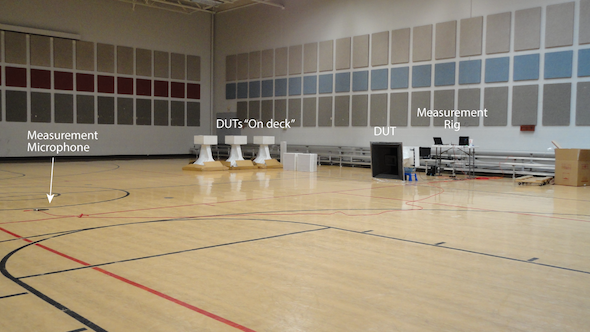
Snoop around the job site to find a large space where you can setup a measurement station. A gymnasium is ideal. Place the loudspeaker on the free throw line and the microphone at half court. Each loudspeaker to be installed comes out of the box and is measured before being moved to the auditorium for installation. Save the measurements to compare with the axial response collected after the loudspeaker is permanently mounted.
Photos 3 and 4 show a measurement session for the loudspeakers for two house of worship systems. We borrowed the gyms and used them for the loudspeaker checkout and direct field equalization. The additional system tuning steps were done after the loudspeakers were installed in the auditoriums.
Photos 3 and 4 – A gymnasium is perfect for setting up a “quality control/direct field measurement” station to check the loudspeakers out before flying.
Gleaning Information
Once you have gone to the trouble of setting this up, a lot of additional information can be gained by making a few extra measurements. I sometimes make the measurement at several equi-spaced distances. Of course the level will drop with increasing distance, but I compensate for that so that the measurements are all the same level. That’s an optional step, and you can get the same information without doing it.
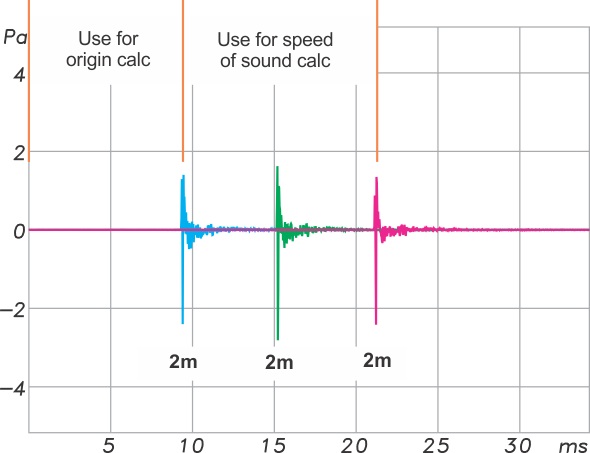
A set of equi-spaced ground plane measurements (Figure 2) can yield a lot of information, including:
– The near-field/far-field transition for the DUT
– The acoustic origin of the DUT
– The speed of sound
– The effect of air absorption as a function of distance on the frequency response
The GP measurement is also an excellent way to find the acoustic origin of the loudspeaker. This is the apparent point of origin for the sound from the loudspeaker. There is no actual point of origin, because the loudspeaker occupies a volume of space. It only appears as a point if observed from a remote distance. Still the acoustic origin can be useful for setting delays and serving as a reference for reconciling polar measurements with the axial response. Figure 2 shows a series of measurements made 2 m apart for a line array box, referenced to the face of the box. Note that the later measurements are equally spaced, but the first arrival has a longer path. The additional time-of-flight reveals the acoustic origin of the loudspeaker, and can be found by converting to distance and measuring from the front of the box back into the DUT.
Figure 2 – A series of GP measurements at 2 m intervals. The DUT must be re-aimed for each to keep it normal to the DUT.
Since the exact distance is known between the three measurements, as is the exact time, the speed of sound can be determined. In this case it was 349 m/s. Do I really need to know that? Not too often, but it is interesting none-the-less.
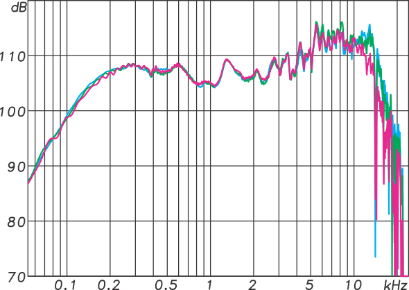
Figure 3 shows the overlaid frequency response magnitudes for the IRs of Figure 2. Each was normalized to 1 meter as part of the measurement process. Since the applied voltage was known, these become the axial sensitivity of the loudspeaker. The blue curve is at 2 m, the green curve at 4 m, and the magenta curve at 6 m. The air absorption difference is apparent from the response fall-off above 10 kHz. A very long (200 ms) time window was used. The magenta curve shows a slight ripple below 500 Hz, caused by the reflection from the nearest building. This can be windowed out, but I left it in as an example. It lets me know that I have maxed out the frequency resolution. This is better data than can be measured in an anechoic chamber, because there is no practical limit on LF response or frequency resolution.
Figure 3 – The overlaid frequency response magnitudes of the IRs shown in Figure 2.
Since the plots overlay almost exactly, I know that all three measurements were in the far-field of the DUT for practically all of its pass band. The differences above 10 kHz are likely due to air absorption. In acoustics, everything becomes “iffy” above 10 kHz.
Conclusion
A large space and the ground plane measurement allow you to acquire a high frequency resolution direct field response without the need for an anechoic chamber. It’s better data that you will ever get after the loudspeaker is installed, and it is needed for configuring the signal processing for the loudspeaker. It’s also a good reminder that loudspeakers have the highest fidelity when placed well away from boundaries. This fact should influence the loudspeaker placements in your system designs. A gymnasium with hardwood floor is perfect. If you do it outdoors you will need a calm day, since a breeze will affect the high frequency response, especially the phase. And as if things couldn’t get better, you don’t even need a mic stand. pb


