When the Volume Knob Goes to the Right
by Hadi Sumoro www.HXAudiolab.com
In this article, Hadi Sumoro presents the basics of sound system design in layman’s language.
Foreword
Following the release of our previous article, “The Volume Knob Also Goes to The Left: A Tale of Loudness”, we received a lot of good feedback along with a number of requests to expand our analysis to the other side of the volume spectrum. And so, in this article, we’re going to ask: how do we turn the volume up properly? This article will explore this question while also discussing some of the basics of sound system design in layman’s language along with easy analogies.
Due to the nature of the intention stated above, this is neither a technical article nor a comprehensive discussion about sound system design. The intention of this article is to help a small venue with a small sound system scale requirement that does not have a sufficient budget to hire a sound system consultant and/or do proper professional installations. In our past experiences, we often received questions about how to provide a functional sound system along with an excuse: “We just want sound and do not have the time/budget to learn the details in-depth”. This article will present a very fundamental approach to how loudspeakers should be placed/arranged without too much technicality and we also hope this article will spark readers to pursue more knowledge about the proper sound system education such as private trainings with a consultant, SynAudCon courses or other similar courses.
The Need of a Sound Reinforcement System
Of course, we need to talk first about why we need a sound system. When you go to a venue, you want to hear the sound equally balanced between the quantity of sound and the overall sound quality everywhere in the audience area. Sitting at the back or side should not matter if the sound system is properly designed, deployed and used. We can briefly conclude that a good sound system should distribute sound equally (quality and quantity-wise), not just simply amplify the sound source level.
Before going further, it is also important to understand that a sound reinforcement system is essentially a sound reproduction system. A typical sound reinforcement system is not meant as a sound enhancement system where it can magically ‘fix’ or ‘enhance’ the sound source. In short, garbage in – garbage out. When the sound source does not have adequate bass, then what is being distributed will not contain adequate bass either. When a singer sings out-of-tune, it will get louder with the sound system and will still be out-of-tune. When someone has a thin voice, the sound system won’t magically change the quality of the voice. Of course, there is additional hardware or software that can be added for specific usage, but the basic intention of a sound reinforcement system is to reproduce and distribute the sound source(s).
A Sound System That Never Fails
“Can a properly designed, installed and optimized sound system fail its function?” This question is analogous to: “Can a good and expensive car be wrecked in an accident?” As sound system consultants, we don’t hear this question asked directly; however, it is important to deliver the message. Yes, a properly designed, installed and optimized sound system can fail. The failure can take on many forms, but here are several examples we often encounter.
The Proper Usage of a Microphone
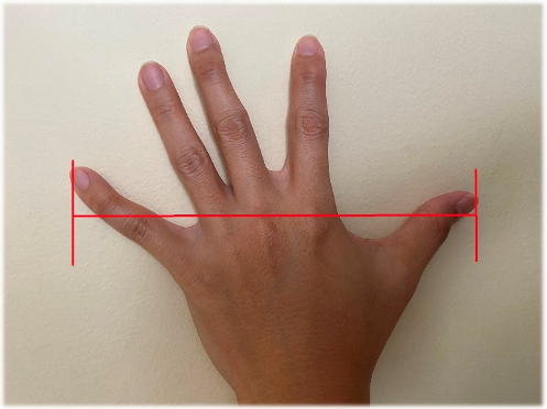
Speakers or singers should speak/sing at a close distance to the microphone. Close distance means no farther than 8in or 20cm. Can’t remember the number? No problem. Simply open and stretch your palm widely as illustrated in figure 1. For a typical adult hand, this is approx. 8in or 20cm. If the mouth/chin to the microphone’s capsule is farther than the tip of the thumb to the tip of the pinky, then it is considered too far and can create audio-related problems such as feedback, unclear reproduction or it can’t be heard.
This matter can be further complicated by the location of the microphone and the discussion may sway too far from the title of this article. A good baseline of microphone usage is simply placing it just in the front of the mouth at a close distance
More Bass!
Since the intention of this article is for a venue with the need of a small-scale sound system, most of these venues may not have a subwoofer to extend the low frequency reproduction, and if they do, they often only utilize small subwoofer(s) with limited output capabilities (read: low-cost subwoofers can’t be ‘that’ loud). It is important to understand the limitations of the installed sound system! Proper optimization can help with loudspeaker protection, however the request for more low frequency boost is very typical. We received a lot of requests to boost the low frequency output when listening to a commercial recording as a sound source (let’s assume a good and well-balanced recording). But, does the recording contain ‘that’ much bass? Remember that the sound system’s job is to reproduce the sound source, not to change or ‘color’ the quality of the sound source. If the recording is lacking bass and one uses an equalizer to add more bass, then playing a recording with heavy bass content may result in too much bass (often referred as muddy sound quality). And depending on how the loudspeaker protection is set up, a high signal (read: very loud) with plenty low frequency content may damage the loudspeaker’s woofer(s).
Turn It Up! I Can’t Hear You!
Ok! Let’s turn it up … properly! Yes, putting a loudspeaker on a pole (typically at/slightly above the head level) is easy. Turn it on, turn the volume knobs to the right (clock-wise) and behold the loud sound! But what does it mean to turn it up properly? As discussed previously, the job of the sound system is not to make sound sources louder, but to distribute it equally. Let’s look at it from a different perspective.
Figure 2 shows two people talking at approx. 1m away from each other without raising the voice. If one carries a sound pressure level meter (a device to measure how loud a sound is in decibel units), this will typically result in a level of 60-70dB, which is a normal conversation level and most of us will feel comfortable. This can be translated to a sound system world: If the speech reproduction is distributed equally at 60-70dB (assuming the background noise is low/not interfering) in the audience area, the feeling of being in the event will be natural like listening to a normal conversation.
In a typical venue, the audience area is not meant for one person only. The audience is spread around the area and the farthest vs closest audience member relative to the loudspeaker can present a problem for a small-scale sound system.
Figure 3 illustrates how a talker speaking with a raised voice may not deliver adequate loudness for the farthest listener, an adequate amount for the listener at a medium distance but too much for the closest listener. This is the very fundamental problem of putting loudspeakers on the floor, on a short pole or on a table. The loudness is not distributed equally.
First, we need to tackle the farthest audience problem by turning up the output. How would you gain more loudness with your raised voice without screaming? How about cupping our palms around the side of our mouth to create a small horn (or tunnel)? In the loudspeaker world, this translates finding loudspeaker(s) with higher sensitivity or maximum output specification.
With more output, the speaker in figure 4 may achieve the goal of providing adequate loudness to the farthest listener. However, it still may not be pleasant for the closest listener because the level may remain too loud to be comfortable. So, selecting a loudspeaker that can be turned up loud enough to reach the farthest listener is important, but the placement is the caveat.
At this point, the reader may sum up that a good loudspeaker layout will provide adequate loudness to those farthest from the sound source while not causing discomfort to those closest to the sound source. So how do we achieve this? The key lies in how high we position the loudspeaker.
The ideal recommendation would be to fly the loudspeaker as illustrated in figure 5. In our past experiences working with small houses of worship, some may be able to retain a contractor/system integrator to fly the loudspeaker safely and do the wiring/cabling. D-I-Y is certainly not recommended due to the safety factor. By raising the loudspeaker and orienting the front projection axis toward the intended farthest audience, it creates a smaller difference in relative distance between the front and back row audience to the loudspeaker. Positioning the loudspeaker this way will result in a more even sound coverage.
The small-scale sound system, where loudspeakers can practically only be placed on a pole can pose a limitation. If the stage/platform is raised, putting the loudspeaker stand on the stage can help to raise the loudspeaker height. To further improve the loudspeaker aiming, practitioners can also experiment using pole mounting with a built-in down-tilt feature. Figure 6 is an illustration from QSC K series where users have a choice of placing the loudspeaker straight or with a slight down-tilt on a pole. This can be done just by rotating the pole mount socket under the loudspeaker.
How about Subwoofer(s)?
The same principle applies to subwoofer. By locating a subwoofer under the stage or in the front-side of the stage, the front row audience may receive louder bass relative to the back row due to the distance. Since the low frequency distribution is heavily affected by the room/walls and flying a subwoofer can be an expensive addition, it is generally safer to keep the subwoofer on the floor. The uneven distribution of low frequencies is not a major concern because the human hearing system is less sensitive to low frequency. For a small-scale sound system, having an evenly distributed loudness in the voice range is much more important than fighting to have an even bass throughout the audience area.
A Long Room with Low Ceiling Height
In general, if the back row (farthest audience to the loudspeaker) is less than 3 times to the front row (closest audience to the loudspeaker), the level difference between front and back row may still be OK. When a small-scale sound system is deployed in a long room with a low ceiling height, the loudspeaker’s throw distance to the back row can be more than three times that of the throw distance to the front row. This layout isn’t preferred and delayed loudspeaker(s) are needed. Delayed loudspeakers refer to additional loudspeaker(s) that are deployed ‘in the middle’ of the audience area. This loudspeaker layout is also typically known as a zoned distributed system, and is also applicable for pole-mounted loudspeakers.
Side note: a loudspeaker’s required throw distance typically refers to the distance between the loudspeaker and the intended farthest audience to cover.
In figure 7, the reader can notice that the throw distance ratio of each loudspeaker to its farthest/closest audience is less than 3:1. Each loudspeaker’s throw distance is illustrated by the green lines. However, there is a caveat: the front loudspeaker(s) will also spray sound to the back rows. Therefore, the half-back audience will receive sound from two sound source locations. This can create an interference problem which may degrade speech intelligibility or sound quality. The loudspeaker(s) that are deployed ‘in the middle’ of the audience area must be delayed (hence the name: delayed loudspeaker or delay ring). The delay time can be added via a digital signal processor (DSP) or by what is commonly known as loudspeaker management system (LMS) processor. The detail of the DSP setup is beyond the scope of this article, but we hope this information can direct the audio practitioners to the right direction when thinking about loudspeaker layout.
What was Being Said?
Speech intelligibility refers to whether the messages played back from the sound system can be understood well enough for the listener to re-tell. Several factors play a part in this. Although a small-scale sound system is usually deployed in a small to medium room, the amount of the absorptive materials plays a key role. When the sound source stops and does not decay fast enough, the room is usually referred as “live” or “echoic” or in a more technical term: reverberant. This happens due to the lack of absorptive materials such as carpet, acoustical ceiling tiles, seat cushions, large cloth decorative banners, etc. Let’s discuss this from a different perspective to understand the proper loudspeaker selection.
Figure 8 shows an effort to read in a large dark room. The darkness will not help the reading effort. Then a small bulb is turned on as illustrated in figure 9. Can you read in this condition? Well, yes and no. When you get closer to the bulb, then it will aid the reading effort. However, if you are standing at the other far end of the room, reading may still not be possible. The next option is using a spotlight. Figure 10 illustrates the use of spotlight at some distance away. This latter arrangement can aid the reading effort if the reading location is inside the light beam coverage of the spotlight.
Side note: reverberation time is the time needed for sound to decay 60dB after it stops playing. When a reverberation time is longer than 2 seconds, it can degrade speech intelligibility.
Loudspeakers have some degree of sound focusing, or in a more technical term: directivity. A loudspeaker with low directivity will radiate sound everywhere, whereas a high directivity loudspeaker will focus the sound dispersion (typically at mid to high frequencies) to its front side.
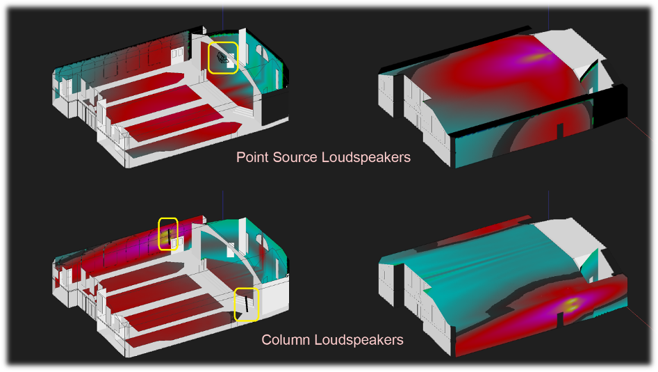
Figure 11 – Bottom pictures: Using high directivity loudspeakers (column loudspeakers) near the front-side of the stage; Top pictures: using regular trapezoidal loudspeakers (point sources) flown in the peak of the ceiling. Yellow rectangles show the loudspeaker locations. The left pictures show the direct sound coverage on the walls and audience areas. The right pictures show the direct sound coverage on the ceiling. The sound level prediction is rated high to low in the following order: yellow – pink – red – cyan (light blue).
A typical trapezoidal loudspeaker is usually a point source type. Point source type refers to a loudspeaker that disperses sound like a sphere that gradually expands. When the size of a point source loudspeaker is large, it may incorporate a large horn. The large horn can help to increase the directivity of the loudspeaker. The use of a point source is shown in figure 11, top pictures. Point source loudspeakers were simulated in the 3D computer model software as if they’re installed near the peak of the ceiling. The pink and red-colored surfaces show where the majority of the sound hit the boundaries. The reader can notice that the ceiling is receiving a lot of direct sound (figure 11, top right picture). Some examples of typical point source loudspeakers can be seen in figure12.
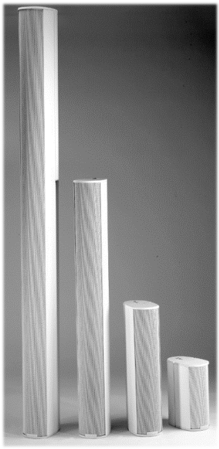
A high directivity loudspeaker is typically large in size for a point source type, or tall if it is a column loudspeaker. Some examples of column loudspeakers can be noted in figure 13. If the reader observes carefully figure 11, bottom right picture, most of the ceiling areas are not red. The high directivity column loudspeakers are focusing sound toward the audience area, not spraying too much sound everywhere else. With a high directivity loudspeaker, the amount of sound reflections can be reduced, resulting in less ‘room sound’. Unlike in the visual world where reflections can be beautiful, in sound system world we want to deliver most of the loudspeaker’s direct sound to the audience, not to the ceiling.
Returning to the light analogy in figures 8 – 10, the light bulb represents a low-directivity point source loudspeaker and the spotlight represents a high directivity loudspeaker. We strongly urge the help of a sound system/acoustical consultant to deal with adifficult reverberant room. If budget is very limited, one can contact a manufacture’s distributor/dealer to do in-situ demonstration of their loudspeakers. This will help to determine which loudspeaker types/models can support the functionality of the room.
More Complications
Sound system design and loudspeaker layout can get very complicated when the room is very reverberant/echoic (read: long reverberation time, typically longer than 2 seconds in the mid frequency range). Let us recall the light bulb analogy explanation: “Then a small bulb is turned on as illustrated in figure 9. Can you read in this condition? Well, yes and no. When you get closer to the bulb, then it will aid the reading effort. However, if you are standing at the other far end of the room, reading may still not be possible.”
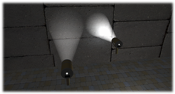
In general, the farther you are from the sound source, the more room sound you will receive. In other words, the level of the sound reflections (read: room sound) can be equal or stronger relative to the direct sound level at some distance away. Figure 14 illustrates a flash light where the light is creating a smaller but brighter cone when the distance is close to the wall, and a much bigger but less bright cone when the distance is far from the wall. With this analogy in mind, it’s important to note that a point source loudspeaker spreads more sound to wider area at a farther distance, hence the room sound can dominate. Room sound isn’t always bad, but the long decay time is typically detrimental to speech intelligibility.
This brings up another point that a shorter loudspeaker’s throw distance may be beneficial in a reverberant room. An extreme example will be the use of pendant-look loudspeaker for a long reverberant room such as a large Catholic church where the historical aesthetic restricts wall mounting of any kind of loudspeakers.
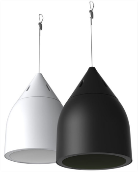
Pendant-look loudspeakers, such as shown in figure 15, are typically point sources. Although they’re low directivity loudspeakers, a low mounting height can minimize the room sound excitation. Figure 16 illustrates such a system which is also appropriate for rooms with low ceiling height. This may require a professional installation but the total project cost may not be too high because pendant-look loudspeakers or in-ceiling loudspeakers are not too costly.

Figure 16 – Ceiling distributed system using pendant loudspeakers can shorten the loudspeaker throw distance, hence minimizing the room sound excitation.
The caveat of this design is the coverage. Let us recall the flashlight analogy in figure 14. When a flashlight is close to the wall, the light cone is small but bright. So, to cover the wall area, more flashlights are needed at that same close distance. By having a short throw distance, a higher loudspeaker quantity is needed to achieve even coverage, but each loudspeaker does not need to run at high level (amplifiers can be less costly).
Conclusion
Sound system design gets complicated easily. Technical study/discussion is required if the readers are interested in knowing more. This short article only discusses common issues that are typically found in small-scale sound system deployment. Turning the volume knob to the right isn’t always ‘that’ simpleand help from a sound system/acoustical consultant may be needed for a difficult room.
This article is inspired by many questions we received as a sound system/acoustical consultant, especially to help owners of small venues to step in the right direction. I would like to thank Pat Brown (www.ProSoundTraining.com) and Chris Devenney for their insights and for reviewing this article prior to publication, and also to William Ladson of Ladson Media for the illustrations. hs

