Idealized Models Help Us Understand Real-World Audio and Acoustic Concepts
The theoretical provides a reference for understanding the physical world
Ideal vs. Real
The fields of audio and acoustics are a mystery to much of the general engineering community. The blend of art, science, objective, and subjective makes audio and acoustics different from other types of engineering.
An example of this is our use of ideal references to describe audio and acoustic components in their most basic forms. These references are theoretical – they do not (and cannot) exist physically, yet we use them to characterize the behavior of real-world behaviors and devices.
The Meaning of “Ideal”
“Ideal” in this context means “idealized.” None of the concepts described below are attainable, because that would require some variable to go to zero or infinity. This can never happen in the physical world. While physically realizable devices can approach these behaviors, they can never reach them. Even so, “ideal” provides a useful reference for what can be achieved.
Here are some examples.
Ideal Acoustical Behaviors:
Free Field

Ideal: An environment where sound waves are free to propagate unobstructed.
Real: Placing a listener or microphone in a free field, it is no longer a free field since the mass of these objects cannot be zero. The interference may be small, but it will always be present.
Practical: Loudspeaker measurements are often made in a free field for producing specifications. The loudspeaker, microphone, or both may be placed on stands of minimal mass to make the interference negligible.
Diffuse Field (Reverberation)
Ideal: A uniformly dispersed sound field where there is no net direction of energy flow. A diffuse field can develop if sound can persist in the room for many seconds. The room must have zero absorption (other than air), and a mixing geometric shape. It must also be large enough to prevent standing waves from forming within the bandwidth of human hearing.
An ideal diffuse field is “statistical,” meaning that it is uniform throughout the space. You can measure the reverberation time or level anywhere and get the same answer. A true diffuse field is noise-like in that there is no information present. Entropy has assured that order has devolved into disorder over time.
Real: All rooms have absorptive surfaces, and an observer in the space would introduce absorption. The air may be the most significant absorber. As such, the room absorption can be low, but it cannot be zero. There will always be specular reflections early in the room impulse response. These are not reverberation.
Practical: Reverberation time formulas assume that the sound field is diffuse. They are widely used because they are simple, but there are few rooms to which they apply. An audio practitioner can go their entire career without encountering a room dominated by a diffuse field. I have only encountered a few. Most rooms have a complex combination of direct, reflected, and reverberant sound at any point of observation within the room. While in theory all rooms have a diffuse field, in practice early and late reflections, along with room modes dominate the listening experience.
Anechoic Environment

Ideal: Anechoic means “without echoes.” A true anechoic environment requires infinite space around the source and listener. A free field is anechoic.
Real: Indoors an anechoic environment can be simulated using sound absorption. Since the perfect absorber does not exist, the specification for an anechoic chamber is that all room reflections must be -20 dB re. the direct sound field at the point of observation at all frequencies of interest. This becomes increasingly difficult with decreasing frequency.
Practical: Anechoic loudspeaker and microphone measurements can be made outdoors if all reflecting objects are at a sufficiently remote distance. In practice, wind and noise are limiting factors. Anechoic measurements can be made in an indoor live environment through use of a time window. A very large space is required to measure low frequencies.
Geometric Acoustics (GA)
Ideal: The use of optical principles to describe the radiation of sound waves. Sound is treated as a beam or a particle where the angle of incidence equals the angle of reflection.
Real: Sound is a wave and will exhibit refractive behavior when an obstruction is encountered. Sound waves wrap around objects in a complex, frequency-dependent way.
Practical: Geometric acoustics (GA) can be used for room acoustics simulations with conditions. Here is an excellent paper on the topic.
Even with its limitations GA is an extraordinarily powerful tool. Users of room acoustics modeling software must understand its strengths and weaknesses for designing auditoriums and sounds systems. By considering the ideal, we can visualize the real.
Ideal Acoustical Sources:
Point Source
Ideal: An infinitely small sound source that emits spherical waves at all frequencies. The sound pressure level (LP) from such a source, when placed in free field, will attenuate 6 dB with each doubling of distance from the source as the sound spreads spherically.
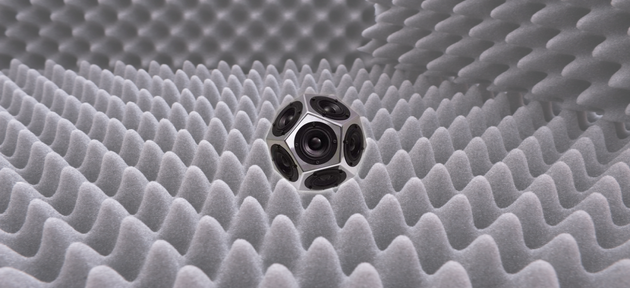
Real: All physically realizable sound sources have mass, and the ideal “pulsating sphere” is usually modeled by an assembly of closely spaced cones of finite size (e.g. a dodecahedron loudspeaker). As a result, there is a near-field where the waves are not spherical. A real-world sound source can be treated as a point source when observed from a distance, since all waves eventually become spherical with increasing distance.
Practical: An ideal point source is omnidirectional. A real-world point source can be directional, yet still emit waves that are spherical when observed from a distance. “Directional point source” is an oxymoron, yet it is an appropriate description of a sound reinforcement loudspeaker.
Line Source
Ideal: A continuous sound source of infinite length that emits cylindrical waves. All points along its length vibrate in-phase. The sound from a line source will attenuate 3 dB with each doubling of distance from the source.
Real: Line sources are typically composed of closely spaced discrete sources. They are not infinite in length. This places high frequency (spacing), low frequency (length), and distance constraints on ideal behavior.
Practical: The typical “sound column” is a line array with a narrow vertical coverage angle and a broad horizontal coverage angle. It can be aimed over nearby listeners to remote listeners, providing even front-to-rear coverage to a wide, deep listening area.
Ideal Electrical Sources:

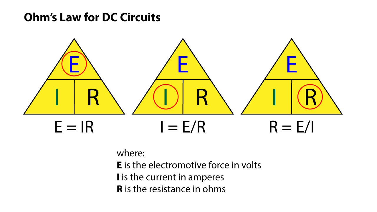
Ideal: Ohm’s Law for DC circuits provides simple relationships between voltage, current, and resistance in a circuit. The formulas can be committed to memory and used to quickly estimate an unknown based on two knowns.
Real: Ohm’s Law for AC circuits replaces R with impedance (Z). Impedance accounts for AC resistance, DC resistance, and reactance. Given its higher complexity, using it for circuit analysis requires a more intense mathematical approach.
Practical: The DC version of Ohm’s Law can be used for AC circuits so long as one understands that the result is an estimate based on a simplified model of the impedance. In field work “close” is often “good enough.” With that in mind, I will describe some ideal DC and AC electrical sources.
Voltage Source

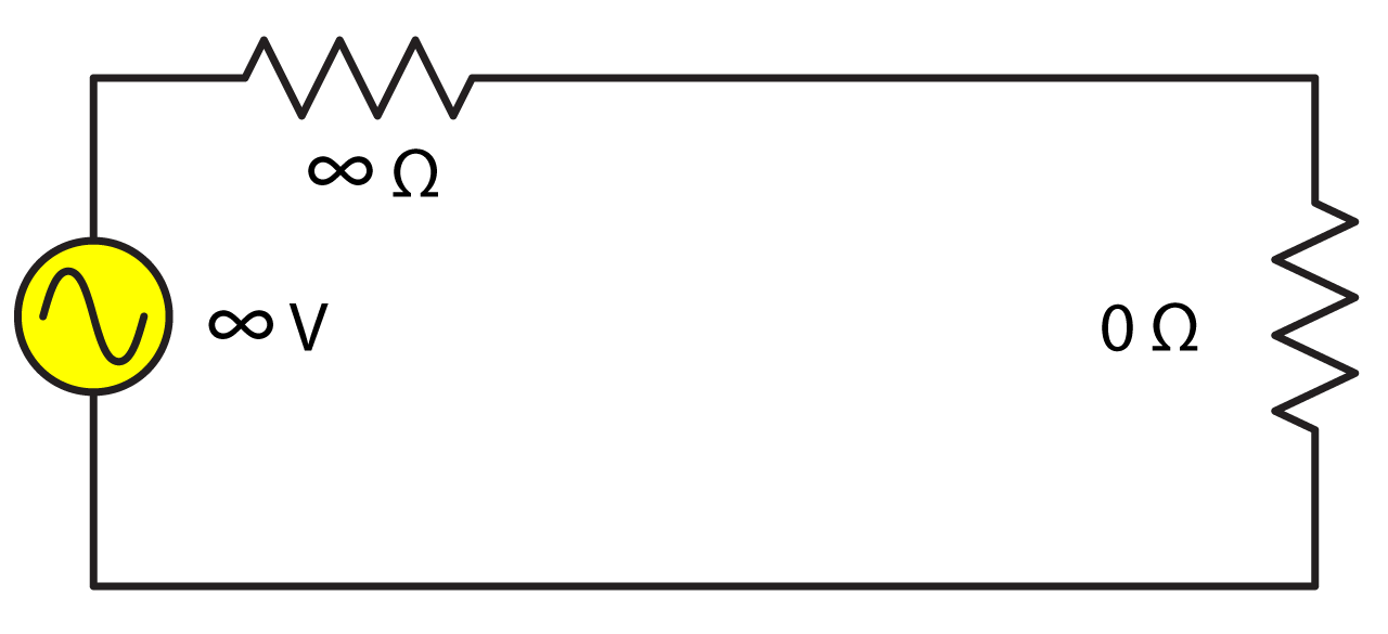
Ideal: A source of voltage and current with zero output impedance. The voltage is established by design and the available current is infinite. While the output voltage of this source can fluctuate (e.g. an audio signal), it not affected by the presence of (or value of) the load impedance for any signal type (e.g. sine wave, noise, speech). This behavior is termed “constant voltage.” If shorted the current from this source would go to infinity.
Real: All physically realizable sources have a non-zero source impedance and finite available current. This places a lower limit on the load impedance for the voltage to remain constant.
Examples: The vast majority of active analog audio components are designed to operate as constant voltage sources within their design limits. These include microphones, mixers, signal processors, and amplifiers.
A “low impedance” audio amplifier can be designed to produce any output voltage, with 140 VRMS being a practical limit. It will typically behave as a constant voltage source down to 8 ohms. It is current-limited by design, and can often drive lower impedance loads if the signal has a high crest factor (peak-to-RMS ratio).
A “high impedance” audio amplifier usually has a higher limit on the load impedance, with the output voltage (sine wave) designed to a standard value (e.g. 25, 70.7, and 100 V). A high impedance amplifier is designed to drive multiple loads in parallel, extremely long cables, or both, typically through a distribution transformer. In contrast to low impedance amplifiers, the load voltage is usually adjusted at the load with a transformer.
Current Source

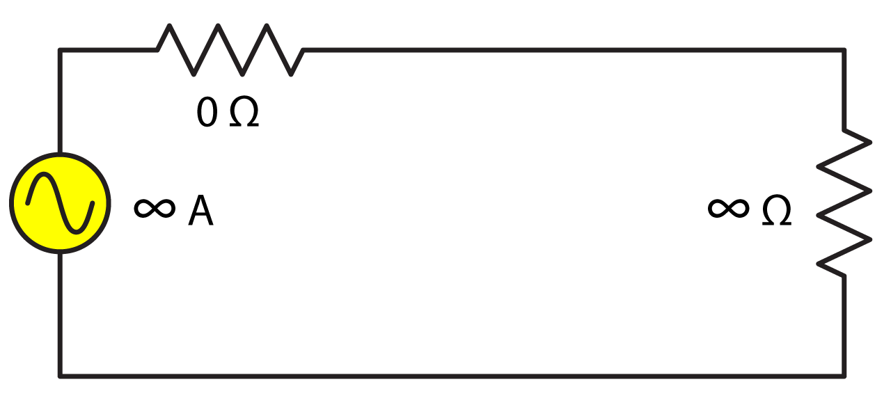
Ideal: A source of voltage and current with infinite output impedance. The current is established by design and the available voltage is infinite. The output current of this source is independent of the load impedance value and the voltage is determined by the load impedance. If shorted the voltage would go to infinity. The “constant current” source is the dual of the “constant voltage” source.
Real: All physically realizable sources have a finite load impedance and finite available voltage. This places an upper limit on the load impedance for the voltage to remain constant.
Examples: Current loop drivers for assisted listening systems. Impedance meters.
Conclusion
In practice, we should expect a source to approach ideal behavior within its design limits. For example, in the case of the ideal voltage source we do not need amplifiers that can source infinite current, but we do need enough current to drive real-world loudspeakers. The body of data produced by the Common Amplifier Format CAF project shows that most low impedance amplifiers emulate ideal voltage sources when loaded at 8 ohms and higher. Since it requires 2x the current to drive a 4 ohm load, many (most) amplifiers will run out of current for some signal types when loaded to 4 ohms unless designed otherwise. Some multi-channel amplifiers can parallel two channels to double the output current.
The “ideal” amplifier serves as a useful reference for understanding, describing, and comparing real-world amplifiers.
It should also be noted that some ideal sources would not be terribly useful for sound reinforcement, even if they were available. Many engineers have spent a lifetime trying to produce the ideal point source loudspeaker, even though it would be the worst possible source for communicating with an audience, either indoors or out due to the energy radiated outside of the audience area. Even though the “ideal” point source is unattainable this does not diminish the usefulness of the concept. pb
