Audio Power Amplifier Maximum Input Voltage

True Line Level Signals Can Clip the Power Amplifier Input Stage
Audio is a mature technology, and older than most. Its roots go all the way back to the telegraph. This would lead one to believe that the field would be highly standardized and essentially plug-and-play by now. Unfortunately, this is not always the case. Here is an example.
Line Level Audio
Ask most audio practitioners for the definition of “line level” audio and they will say “+4 dBu” which is 1.23 Vrms. That is a defensible answer and it is why many mixers and DSPs use this (or a close value) as their “nominal” input and/or output level. It’s also why most professional power amplifiers use 1.2 Vrms (or a close value) as their input sensitivity, as it will drive the amplifier to its full output voltage. Feed it a higher voltage and the amplifier clips.
Signal Peaks
Unfortunately, there is a 20 dB discrepancy in this assumption. The +4 dBu audio signal from the mixer and DSP has signal peaks that exceed the nominal level by 20 dB or more. This is why the mixer and other professional line level components have maximum output levels at or near +24 dBu when signal peaks are considered.
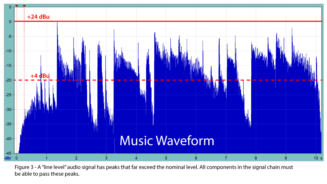

In a typical sound system the mixer is operated at +4 dBu, with 20 dB of “peak room” making the maximum output level +24 dBu. Most DSPs can handle this level without clipping. Most default to “unity gain” which means that the output level is the same as the input level. A problem shows up when we get to the power amplifier. If its input sensitivity is +4 dBu, then the signal level from the mixer (or DSP) is 20 dB higher than what is required to drive the amplifier to its full output voltage. “No problem” you say, because the amplifier’s input can be desensitized by reducing the input attenuator by 20 dB – a “standard” gain structure practice. Now +24 dBu input (the level of the signal peaks) will cause the amplifier to reach clipping, and all is good. Or not.
Most assume that reducing the amplifier’s sensitivity by 20 dB allows the amplifier to handle 20 dB more input voltage. That’s how it should work, and it used to be a common practice. This is no longer necessarily the case, and it can lead to serious gain structure issues in modern systems. An increasing number of power amplifiers have input stages that clip at or near +4 dBu, regardless of the sensitivity control setting. So, even if you turn it down to avoid output stage clipping, the input stage is overdriven by a true line level signal, one whose signal peaks approach +24 dBu.

Remedies
There are several possible remedies. I’ll start with the best solution and work down.
- I’ll give a shout out to Bose for designing amplifiers that have switchable input sensitivity values of 0, 4, 12, and 24 dBu, with a max input voltage of +24 dBu. The PM series is one of the few power amps I have tested whose input circuitry can handle a full professional line level signal.

Figure 4 – The control software for the Bose PM Series provides user-selectable input sensitivity.
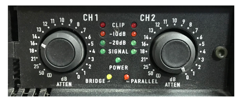
Figure 5 – The QSC PL Series provides detented input sensitivity controls. When reduced, the amplifier can handle higher drive voltages.
- Passive attenuators can reduce both the signal and noise at the output of a mixer or DSP, and allow the amplifier to be operated at its maximum sensitivity setting. This is a good option from a gain structure point of view, but passive attenuators are a kludgy solution for large systems, and they can degrade the common mode rejection of the amplifier. None the less, I find them quite useful for small systems and for powered loudspeakers.
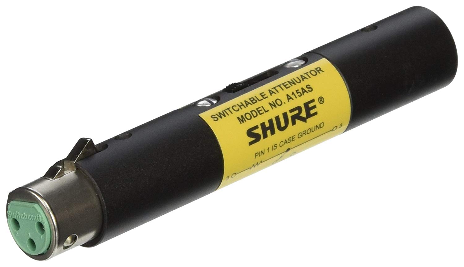
Figure 6 – A passive attenuator can be used to reduce the drive level to the power amplifier.
- Since DSPs have adjustable output levels, the required level reduction can be dialed in there. This has become common practice and it is possibly the best compromise. The downside is that the DSP’s noise floor is typically not reduced by the output level control, so you are compromising the signal-to-noise ratio (SNR) by reducing the output signal level. In a day where everyone is enamored by high dynamic range it seems strange to me to take such a hit on system performance. The compromise may not be noticed in many systems since the noise floor of the signal is significantly higher than the noise floor of the DSP. In that case, the DSP output level can be attenuated without sacrificing the the SNR of the finished system. In effect, less than ideal SNR at the system input is masking a problem that occurs later in the signal chain. But, it remains a problem for systems in quiet environments, such as padded auditoriums, studios, and home theaters.
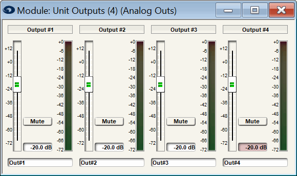
Figure 7 – The Symetrix Prism has precisely adjustable output levels, allowing the output voltage to be reduced to avoid clipping the power amp input. Note that reducing the output signal level may also reduce the signal-to-noise ratio.
- It is fairly common to find power amp input stage clipping voltages of 4 Vrms (+14 dBu). So, if the input sensitivity is +4 dBu, the sensitivity control can be set at -10 dB re. maximum sensitivity to make the amplifier clip when driven at +14 dBu. That’s a step in the right direction, but it will still be overdriven by 10 dB by a +24 dBu drive signal. Then there’s the problem that many contemporary amplifiers have “trim pot” sensitivity controls, so there is no visual reference for setting it to -10 dB. It can be set with a voltmeter or scope, but it will only be an approximation. And what if you have a rack full of these amplifiers? In many modern systems “maxing out” the amplifier’s sensitivity controls is the only practical solution.
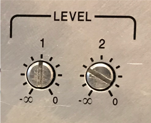
Figure 8 – Trim pots can control the gain of the power amp, but it may still be possible to overdrive the input circuit. Achieving the same trim setting for multiple amplifiers is tedious.
- Some sound systems do not have a DSP between the mixer and amplifiers. Increasingly the house EQ is in the digital mixer. I just did training at a major theme park where this is their standard practice. Now we have to throttle back the mixer to avoid clipping the amplifier inputs. Yes, it “works” but the SNR compromise is now in the mixer. Also, we lose operating range in the mixer’s output faders and meters and the system noise floor is audible to the audience.
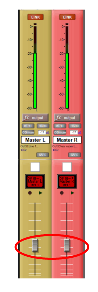
Figure 9 – The master faders of this Digico mixer must be reduced to avoid overdriving the power amps. Note that the output level must be kept below -20 dBFS.
And finally we come to the “main street” solution to the problem. Run the DSP at “unity,” max out the amplifiers, and set the house SPL with the mixer’s output fader. Yes, we get sound, but this sacrifices SNR in both the mixer and the DSP, and applies maximum amplifier gain to a compromised signal.
Conclusion
Some will think I’m being nerdy in pointing out this problem, and some do not even see it as being a problem. We’ve gotten so used to non-optimal gain structure in sound systems that we not only live with it, we expect it. That’s fine. Everyone still gets paid. But anyone paying attention should be bothered by a problem like this existing in a modern technical system. We have audio components that are intended to form a system with incompatible signal levels – mixers that output +24 dBu (or higher), and amplifiers that can’t handle it. The fix is a laundry list of work-arounds that are needed to produce functioning sound systems.
It’s no wonder that IT people find audio confusing. pb
