Low-Frequency Directivity and Arrays
This article is an attempt to quantify the theory and application of low frequency arrays for sound reinforcement applications.
The lack of low frequency directivity is a problem that plagues many sound systems. It is usually manifested by poor gain-before-feedback at low frequencies where the loudspeaker radiation becomes either omnidirectional or directional with a radiation pattern that is unsuitable for the array’s position.
It is possible and even feasible in some applications to achieve low frequency directivity by horn loading loudspeakers, but the  shear physical size of “bass horns” makes them impractical for many applications. It is a well-documented fact that low frequency directivity can also be achieved by constructing arrays of direct radiators positioned in such a way that their interaction allows the radiated energy to be concentrated in one or more directions. This information is not new, and was well documented in the early days of motion picture theater systems in the first half of this century. What is surprising however how often these principles are overlooked by system designers, evidenced by the number of commercially implemented systems that violate low frequency array principals.
This Tech Topic is an attempt to quantify the theory and application of low frequency arrays for sound reinforcement applications, and is essentially a “repackaging” of an existing knowledge base using some modern tools for presentation and clarification. The Tech Topic does not address the modal response of the room, and makes the assumption that the spaces in which these arrays might be implemented are very large with respect to the array. In other words, free field radiation conditions are assumed in which the inverse square law correctly describes the propagation of energy as a function of time and distance. The other assumption made is that the individual radiators that make up the arrays are themselves “point sources” radiating energy equally in all directions at the frequencies of interest and much smaller physically than the wavelengths being radiated. A benefit of this approach is that the resultant arrays are independent of manufacturer, and can be implemented using most any low frequency loudspeaker and enclosure that approximates a point source.
A number of excellent software modeling tools are available for investigations of this type, and have served designers for a number of years. The application chosen for this Tech Topic is ArraySHOW™ from Mark Ureda and EVI Audio, chosen mainly for its simplicity, speed, and graphic output capabilities.
Background theory
For our purposes, and array is a combination of two or more low frequency point sources in close enough proximity to allow acoustic coupling at the frequencies of interest. The below graph shows the relationship between acoustic wavelength and frequency, and while it would be possible to speak in terms of frequency alone the use of wavelength provides much more insight into the processes.
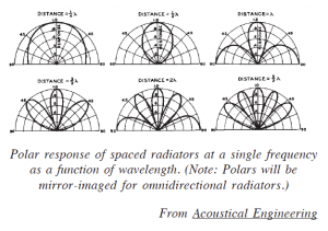
Harry Olson, in his 1939 book Acoustical Engineering documented the interaction of omnidirectional radiators when placed in close proximity. The graphic at right provides some insight into this interaction as a function of the fractional wavelength spacing of the devices. The lobes result from the time/distance offset between the energy arrivals from the radiators at various positions around the array. The principle of superposition is used to combine the responses of the devices as a function of the phase offset between them resulting from their physical spacing and the point of observation. 
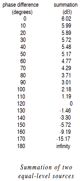
From the chart at right, note that the energy summation between two devices can be as high as 6 dB (resulting from in-phase summation) or can result in complete cancellation when the radiated waves are 180 degrees out of phase. Cancellations of this type indicate that the energy has been radiated in a different direction, and does not mean that the energy no longer exists. Low frequency arrays are effectively “energy steering” systems, that can be used to keep the energy on the audience and off of the microphones.
Performance spaces that require sound reinforcement normally have several possible locations for the low frequency arrays. These are:
- Directly above the stage
- Directly in front of or under the stage
- Stage right, stage left or both
It would be impossible to construct one specific low frequency array whose energy radiation is optimized for all of these positions. For instance, an array over a stage would need to radiate minimal energy straight down, yet maintain a broad horizontal coverage pattern. The same array placed on stage left or stage right could radiate excessive energy to allow distant miking – an application where a null toward the stage might be desirous. The first step of implementing an array therefore becomes the decision as to where it must be placed; something determined by the  physical constraints and conditions that exist in all venues.
The variables that determine the polar response of an array are:
- 1. The number of devices
- 2. The spacing between the devices
- 3. The frequency (wavelength of interest)
- 4. The time offset between the devices (delay)
- 5. The polarity of the devices
- 6. The relative levels of the devices
All of these parameters can be readily input into the computer, and the polar responses generated.
The following pages depict some arrays that have been optimized for each type of placement. pb


