Piezo Magic – Accurate Gain Structure Using a Common Device
Pat Brown will show you a way to set gain structure by using a piezo tweeter.
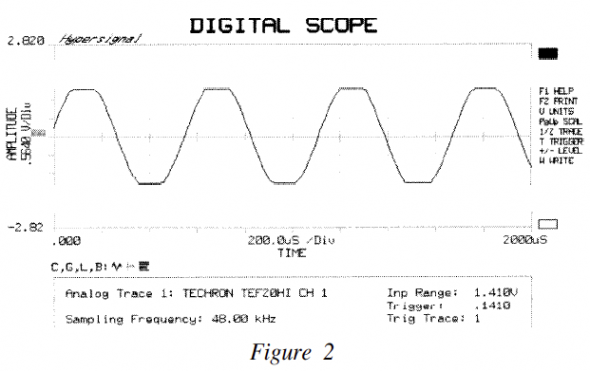
In order to set the gain structure of a signal processing chain properly, it is necessary to determine when each device (mixer, eq, etc.) can no longer provide an increase in output signal with an increase in input signal. This condition, known as clipping, indicates that the limits of voltage swing for that device have been reached. Once determined, a voltage measurement can be made to determine the Eout for the device. Traditionally, this task has been performed with an oscilloscope, an instrument that displays voltage vs. time on its screen. Eout is easily determined by inputting a sine wave into the system (unloaded) and observing the waveform on the scope (Fig. 1). As the input is increased, the waveform will flatten out when the maximum Eout is reached (Fig. 2).
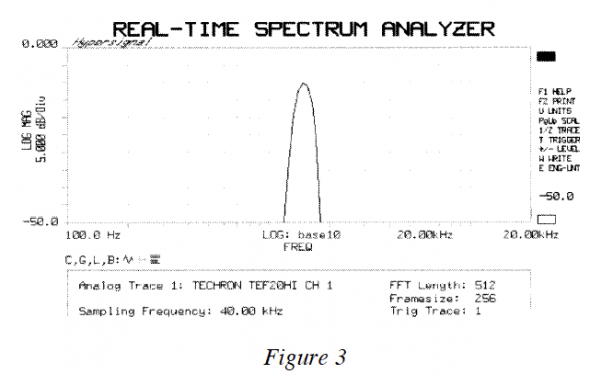
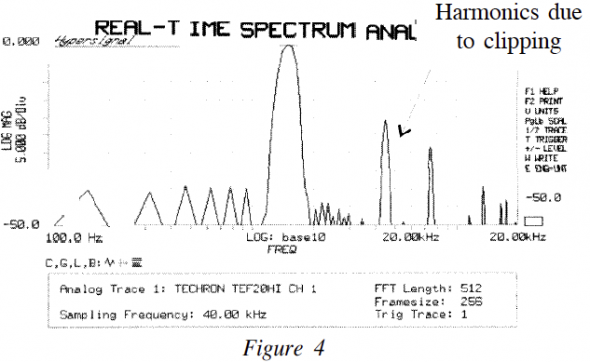
It is also interesting to observe this phenomenon in the frequency domain, where the clipped signal produces harmonics that were not a part of the original test tone. This explains why clipping is such an audible effect, and why it should be avoided (Fig. 3 and 4).
The audible artifacts of clipping provide us with another, much less expensive, method to determine Eout. The solution presents itself when the problem is described in detail. In short, a method is needed to monitor the output of a line level device for the presence of the odd harmonic artifacts of clipping. The monitoring device should appear as an open circuit (high impedance) to the device under test at the fundamental frequency used as the system input. A further benefit would be that the monitoring device should be accurate, inexpensive, and readily available. Better yet, if the device were passive, it would require no external power source to complete its task.
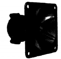
All of these requirements are fulfilled nicely by the common piezo tweeter. This voltage-sensitive high-frequency device is excellent for reproducing the harmonic by-products of clipping. The method I use is to select a test frequency below the passband of the piezo tweeter. This ensures that the impedance will be high (inversely proportional to frequency) and that the fundamental (400 Hz works well) is not audible during the test. As the input signal is increased, the piezo will sound out loudly when the maximum Eout (and the resultant clipping) is reached. Bridging a voltmeter across the output at this point will yield Eout.
For quick system calibrations, it may be unnecessary to actually measure Eout. Simply bring the mixer to clipping, move the device to output of the equalizer and bring it to clipping, and proceed to the output of the system in this manner. Once completed, the needed system headroom can be set with the trim control of the mixer.pb


