Axial Sensitivity – Sense and Sensitivity
One of the many specifications included in loudspeaker specification sheets is the Axial Sensitivity of the loudspeaker. This article clears up some confusion on this topic.
One of the many specifications included in loudspeaker specification sheets is the Axial Sensitivity of the loudspeaker. This specification tells how much output level the loudspeaker will produce at a reference distance when driven with a known input signal. The axial sensitivity specification typically reads xx dB 1W/1m. This implies that the loudspeaker will produce xx dB sound pressure level when measured at a distance of one meter, on-axis, with a 1 watt input. Confusion arises when we dig into the specification. What kind of signal is applied? Does the measurement distance affect the results? Can we really describe the sensitivity of a loudspeaker with one number and other questions? This article will address some of these concerns and attempt to clarify this specification starting with the input level to the loudspeaker.
The Drive Signal
The 1W/1m axial sensitivity specification implies an input of “one electrical watt” to the loudspeaker terminals. Since power is determined by
W = E2/R
where W is power in watts
E is electromotive force in volts
R is resistance in ohms
then we need to know the impedance of the loudspeaker and the input voltage to the loudspeaker as well as the phase angle between the voltage and the current in order to determine how much power the loudspeaker is dissipating. The impedance of a loudspeaker varies with frequency, so which frequency, or band of frequencies should be used to measure the sensitivity? The input voltage can be held constant thanks to the design of most modern power amplifiers as constant voltage sources. Measuring the impedance curve of the loudspeaker is straightforward, but the resulting curve doesn’t really indicate the best value to reference the voltage to for a “one watt” input.
First Try
One method is to take the minimum impedance in the usable frequency range of the loudspeaker and set the input voltage to get one watt at that value. Then everywhere else in the frequency range, the power is not one watt.
Second Try
Another method might be to vary the signal voltage along the impedance curve to produce one watt everywhere, but that would require a wildly fluctuating input signal and every loudspeaker would require a unique signal.
Third Try
A final method, and one that is generally accepted, is to select the input voltage based on a nominal impedance, eight ohms for example; the input voltage would then be 81/2 = 2.83V by Ohm’s Law. The power will be different for every frequency, but the voltage won’t change and based on the selected nominal impedance, the power can be called “one watt.” That is a nominal wattage based on a nominal impedance and a set input voltage. In this case, it might be wise to change the name of this specification from “1W/1m axial sensitivity” to the “2.83V/1m axial sensitivity” for clarity. It all comes back to the applied voltage. As a side note, the power dissipated is strictly a byproduct of the voltage and impedance and has nothing to do with the output level of the loudspeaker, but I digress…
The Right Distance
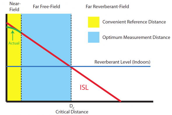
The measurement distance is important because at one meter many loudspeakers no longer look like point sources to the measurement microphone; their physical size is large with respect to the measurement distance. This would be like to trying to measure the SPL of a whole band from a point one foot away from a guitar amplifier on stage – the guitar amp would dominate the measurement. This may result in skewed sensitivity numbers because if the observation distance is too close to a multi-way loudspeaker one of the devices may contribute more than the others to the measurement. It is generally acceptable to measure at a minimum distance that equals or exceeds three times the largest dimension of the loudspeaker; if the loudspeaker is 0.8 meters diagonally, then an appropriate measurement distance would be three times 0.8 meters or at least 2.4 meters. The results from the larger measurement distance then need to be normalized to one meter using the inverse-square law (which treats the device as a perfect point source). If we measure at two meters (a nice round number), then the one meter Axial Sensitivity would be six dB higher than the results measured at two meters. The larger measurement distance serves the modeling software well, because it places the results in the far field of the loudspeaker and allows extrapolation to greater distances using the inverse-square law. Since the measurement distance is significantly larger than the largest dimension of the loudspeaker, then the loudspeaker begins to appear as a point source at the measurement location.
One-Number Ratings
Usually an Axial Sensitivity measurement is made with a swept sine wave input signal. The acoustic signal at the microphone is compared to the input and since the input signal is a constant voltage then any deviation shows up on the sensitivity curve. The Axial Sensitivity curve is the same as the axial frequency response of the loudspeaker because it really is the frequency response on axis but normalized to a standard distance and drive voltage. The loudspeaker sensitivity is a function of frequency, but system designers often like a single-number rating at the early stages of the design process. The single number can be found by averaging the 1/N-octave band sensitivity ratings. This gets the design process started and the designer can refer to higher resolution sensitivity plots to refine the design decisions.
When reading a loudspeaker specification sheet, it is important to understand how the specifications were generated. Hopefully this article has helped the reader understand more about Axial Sensitivity and how it is measured. jj


