Line Array Checkout
by Pat Brown
Pat Brown give you some tips on how to checkout each box of a line array.
 Your multi-box line array looks great. You’ve seen them on TV, but now you are standing in front of a real one, expecting the best sonic experience of your life. You play a favorite music track, but something doesn’t sound right. You check the DSP settings, and then the aiming. All looks good, but it still doesn’t sound right. Now what?
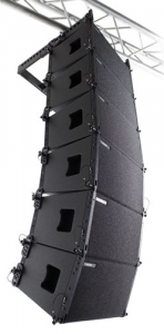
The multi-box line array is a system of full-range loudspeakers, arranged to allow variable vertical coverage control via the shape of the array. The boxes are usually identical and fed the same signal, often by paralleling several boxes onto a single amplifier channel. The horizontal coverage of the array is that of a single box, since there is no multi-box interference in the horizontal plane.
These popular line arrays tend to be expensive since each box is a full-range loudspeaker. Some models use loudspeakers that are internally powered and processed. Alternately, the power amps and processing may be external to the loudspeaker itself, housed in an equipment rack. Yet others use boxes with internal passive crossovers, so that the amplifier channels operate full-range.
Modeling the Coverage
The multi-box array is acoustically complex and requires software for modeling the coverage. Some manufacturers provided proprietary software. Others use third-party, specialized programs, such as EASE Focus. These programs model only the direct field, and are designed to quickly provide the answers to:
- How many boxes?
- What array curvature?
- What trim height?
On a tour, the answers to these questions may change from night-to-night.
 Figure 1 – EASE Focus II direct field modeling program.
Full acoustic modeling must be done in room modeling programs, such as CATT-Acoustic, EASE, Bose Modeler, Odeon, and others. These require more knowledge on the part of the modeler, and can allow deeper investigations into the array’s performance.
All of these programs require at least one box of the array to be measured. The boxes are stacked up in the model and the complex interference between the boxes is calculated. The results are projected onto one or more audience planes. The programs assume that the line array elements are identical. In other words, Array XYZ is made up of multiples of Loudspeaker ABC, but only one Loudspeaker ABC is actually measured. This gives a good approximation of the coverage, but it is an approximation. There are several variables that the modeling cannot account for, and these nibble at the accuracy of the predicted response.
Check the Boxes!
No matter which line array type, it is important for the installer to test each box before arraying it, and then periodically afterwards. The large number of transducers and connections increase the likelihood of errors. Consider a 16-box array of 3-way, triamped full-range loudspeakers. That’s 48 transducers, and 48 potential failure points. Since a line array is a system, a single component failure or mis-wiring changes the response of the entire array, and often dramatically so.
Passive line array elements should be checked for proper polarity, impedance, and axial transfer function.
Active, multi-amped line array elements need the same checks, but for each component in the box.
A powered, internally-processed line array element requires an axial transfer function at a minimum.
All measurements should ideally be performed in the far-field of the device, and the data should be anechoic.
Speeding the Process
While this sounds time consuming, it needn’t be. Since site time is a precious commodity, there are ways to speed the testing process. My preferred method is to check one box of the array in detail, and then use it as a reference to check the other boxes against. This requires only an axial frequency response magnitude of the remaining boxes, since any polarity (relative), wiring, or component issues will be evident in the response. If the comparison shows an irregularity, the complete check can be performed to troubleshoot it.
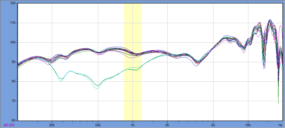
Figure 2 shows the overlaid frequency response magnitudes of a 16-box line array (One array of 4 total). The first box was tested in detail. The others were overlaid for comparison. These were the final results, after several polarity corrections and driver replacements.
 Figure 2 – An overlay of 16 line array boxes. Note that the measurement name (shown at bottom) is the box’s serial number. (www.wavecapture.com)
Workstation Setup
Since a lot of heavy lifting and a large time window are required, a ground plane measurement is the most practical approach. Here is an article with the details. Setup a workstation on a large, flat floor plane. Mark the microphone and loudspeaker positions with gaff tape, and set the box angle with an appropriate prop, securing it so that it doesn’t change positions as the boxes are handled. The amplifier and DSP need to be appropriate for the box, with the same units used to test each box. Only the loudspeaker is changed.
Figure 3 – (left) The GP workstation for a recent project. A piece of masonite was taped to the carpet to provide a reflective surface for the microphone. (right) The line-up of array boxes waiting to be tested.
Figure 4 – The overlaid responses of one of the remaining 3 arrays, this one with three mid-range driver failures.
Figure 5 – The overlaid responses of a 6-box array that I recently tested as a demonstration at AES Brazil. One of the six boxes had a HF transducer issue.
Once the workstation is setup, it should take no more than a minute or so to check each box. Once each box is tested, it can be added to the array (Figure 8). Once the array is assembled it becomes very difficult to test the boxes individually, since there are often several paralleled on a single amplifier. The only chance that you will ever get for an anechoic axial transfer function is prior to the assembly of the array.
Figure 6 – The empty stage provided a good ground plane environment for the AES Brazil demo.
Figure 7 – Once the array was flown, axial measurements were made at several listener distances. An iPad cover provides a smooth surface for the microphone.
It is important to note that the axial frequency response magnitude will only show polarity issues between components within the box (relative polarity). It is blind to the absolute polarity of the box as a system. The impulse response (time domain) or phase response (frequency domain) can be used to reveal absolute polarity issues.
The Array Build and Final Equalization
Once each box is tested, it can be added to the array. The box angles and trim height values are taken from the modeling software. Since the entire audience may be in the near-field of the array, multiple measurement positions must be averaged when performing the final equalization. Since nearly all line array boxes have components that are offset in the horizontal plane, interference lobing will be present. This should not be allowed to influence the equalization. I suggest 3-4 on-axis measurements at several distances as a good place to start.
Figure 8 – The install crew builds the array from the boxes.
Conclusion
What is the likelihood of finding problems? I have never tested a multi-box line array where everything checked out perfectly. If errors are ignored, the array will never function at its potential. The system installer or operator may try to paint over the issues with equalization, making matters even worse. Verification of each box provides the assurance that the array is operating at its full potential. If something doesn’t sound right, only after testing the individual boxes can you can be confident that it is not a system issue. pb


