The Loudspeaker Toaster Test Revisited
by Pat Brown
It’s been nearly a decade since I cooked up the Loudspeaker Toaster test for finding the maximum input voltage EMAX to a loudspeaker. If you are already familiar with the procedure, read on. If not, here are a couple of links to get you up-to-date.
Loudspeaker Toaster – An Abbreviated Power Test You Can Do At Home by Pat Brown
Loudspeaker Maximum Input Voltage Test Results by Charlie Hughes
The Toaster Test is a non-destructive (usually) method for quickly and accurately determining the EMAX of a loudspeaker based on its thermal limits. The test itself is relatively unchanged since its inception. One of its strengths is that many choices exist regarding the instrumentation used to conduct it. If you have been involved in audio for awhile at the technical level, chances are you already have everything you need. I have refined my own process a bit from the method described in the original article.
The Gear
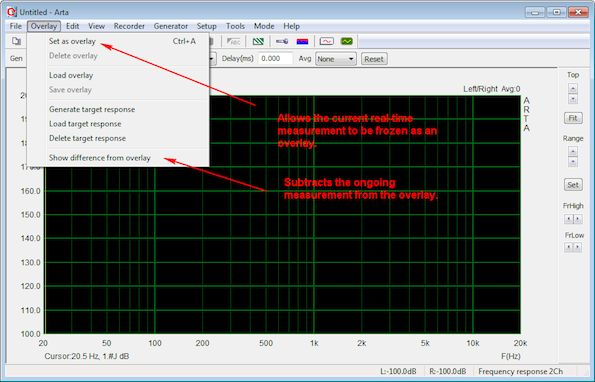
The original Toaster Test used an old version of SmaartLiveTM to monitor the transfer function of the device-under-test (DUT). Subsequent versions of SmaartLive do not support the needed “Subtract from Reference” feature, so I migrated to ARTATM. See Figure 1. Any dual-channel FFT analyzer with a “Show Difference from Overlay” feature should work.
Figure 1 – ARTA is used to monitor the response of the DUT.
I now use an NTI MR-Pro as the program source. It displays the drive level to the amplifier in dBV (or dBu), and allows precision incrementing of the drive level with its rotary encoder. The balanced XLM output is also nice. Pink noise is on board, but you can add a preferred noise type by importing a WAV file. I typically use IEC noise, but there are many choices.
My voltmeter-of-choice is the Audio Precision APx515. The reasons include
1. It handles higher voltages than what can be fed to a loudspeaker.
2. It has flexible averaging algorithms to get a stable measurement of the high crest factor noise stimulus.
3. It can track the voltage over time.
You can monitor the amplifier’s voltage with MUCH cheaper meters. Just make sure yours has adequate bandwidth and is True RMS.
As an additional step. I now measure the SPL of the DUT during the test. This is not necessary for finding the MIV, but it provides some useful information that I will describe in the next section. The sound level meter (SLM) is the NTI XL2.
The Procedure
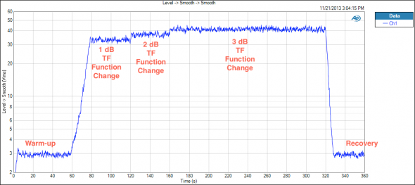
I document the entire time span of the test, using the Measurement Recorder test of the APx515. The time span is 5 minutes, as displayed on the x-axis of the measurement screen. Figure 2 shows the graph produced during the test (Red annotations added).
1. The measurement microphone is placed 1 m from the DUT. If the SPL is too high at this distance, it can be moved further away, and the measured SPL normalized to 1 m using the inverse-square law (add 6 dB to the measured SPL for each doubling of distance).
2. The start voltage for the test is 3 Vrms. This should produce a reading on the SLM that roughly agrees with the average sensitivity of the DUT. Let it run for about one minute, store the measurement as an overlay in ARTA, and then put ARTA in the “Show Difference from Overlay” mode.
3. Gradually increase the drive voltage until the transfer function (TF) begins to deviate from 0 dB. There’s no need to ramp it up slowly over time. You can see from Figure 2 that I get there pretty quickly.
4. Let it run for one minute, and then increase the drive voltage by 1 dB.
5. Repeat until the transfer function changes by 3 dB.
6. Let it run for 3 minutes at this drive level. If the TF remains stable, you have found the EMAX for the DUT. Record the SPL at the EMAX. This is the maximum continuous SPL that can be produced by the DUT, and it serves as a sanity check for the calculated levels in your room modeling program.
7. Back the drive level down until you are back at 3 Vrms to the DUT. The TF should return to 0 dB after a few minutes. This is confirmation that the DUT has survived the test and that you have a meaningful EMAX.
Figure 2 shows a graph of the amplifier voltage vs. time. This DUT can handle 40 Vrms for at least 3 minutes without permanent change to its response. Of course, the test can span as much time as you like. I use 3 minutes because it simulates a temporary increase in level, as might occur at the end of a concert or show. You can pick any criteria you like for terminating the test.
I make notes of the SPL at the beginning and end of the test. Here’s an example from a recent session.
MIV Start: 99 dBZ-slow @ 3 Vrms (IEC Noise)
MIV End: 119 dBZ-slow @ 40 Vrms
In this example, the “gain above average sensitivity” can be found by calculating the level difference between the two voltages.
G = 20 log (40/3) = 22 dB
Better yet, you can simply subtract the start SPL from the end SPL.
G = 119 – 99 = 20 dB
The 2 dB discrepancy is due to the fact that the loudspeaker is in power compression at the end of the test, so the last few level increments may not increase the SPL, even though the amplifier voltage continues to rise. This behavior is loudspeaker-specific, as the 3 dB change may be narrow or broad band. The SPL measurement takes that into account.
If the result seems like an approximation, it is because it is an approximation. “Close” is the best we can do when assessing the thermal limits of a loudspeaker. Fortunately, close is good enough for the intended application – amplifier selection and maximum SPL assessment.
The “time record” and SPL additions to the toaster test have proved both enlightening and useful.
Figure 2 – Tracking the amplifier voltage vs. time.
Using the Data
The MIV is entered into the data file for the loudspeaker. The Common Loudspeaker Format (CLF) file viewer displays the EMAX, the gain above the reference sensitivity, and the required amplifier rating in watts to produce the EMAX. The EASE GLL format computes the maximum 1 m SPL from the EMAX.
The Toaster Test refines the procedure for determining the EMAX of a loudspeaker. The EMAX can be used to calculate a power rating in watts, using the rated impedance of the loudspeaker. It is important to remember that the rated impedance treats the loudspeaker as a fixed-value resistor, which of course it isn’t. This is why it is better to track (and specify) the RMS voltage when assessing the signal handling capability of a loudspeaker. pb


