High Voltage Audio Measurements
by Pat Brown
 A voltmeter used for audio work should ideally be able to handle the highest voltage likely to be present in a sound system. We don’t want to fry the input stage of our expensive meter. What voltage must it handle? The largest available audio power amplifiers have rail voltages of about 200 VDC for a single channel. Configure one of these for bridged-mono operation and we are at 400 VDC. Of course, only AC comes out of the amplifier. A square wave (unlikely to happen) could reach this rms voltage. A sine wave (more likely to happen) could reach 280 Vrms, which makes it a defensible target voltage. Even if you don’t work with multi-kilowatt power amps, you can encounter high voltages in transformer-distributed loudspeaker systems.
Voltmeters designed for use by electricians can usually handle up to 600 Vrms, far more than those designed for use in audio systems . Here is the Maximum Input Voltage (MIV) for some popular audio voltmeters.
Audio Precision APx515TM: 125 Vpk
NTI XL2TM: 25 Vrms
iAudioInterface2TM (for iPhone/iPad/iPod): +40 dBu
Note that none of these devices can measure the amplifier described above. To make matters worse, the specifications are often obscure by not including both peak and rms ratings.
Here are some ways to beef up the MIV of your audio voltmeter, using the above instruments as examples.
A Solution for the Audio Precision
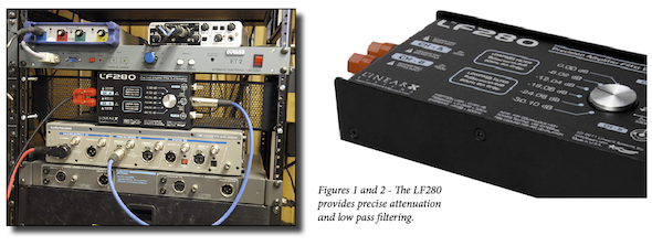
A sophisticated solution is the use of a passive network between the amplifier and voltmeter. Langston Holland turned me onto the Linear-X LF280. It has a calibrated stepped attenuator that can provide up to 30 dB of attenuation. It also includes a low pass filter that removes the out-of-band switching frequencies generated by Class D amplifiers. Given that AP analyzers are pretty pricey, this is a relatively low cost add-on. It’s rather bulky, but so is the AP. The LF280 is accurate, purpose-built, and nicely packaged.
A Solution for the NTI XL2
The LF280 is WAY to big to live in my travel kit, where my XL2 meter resides. This solution needs to be smaller and simpler. I decided to use the RCA input jack for measuring amplifier outputs. This is an unbalanced input, with no possibility of sourcing phantom power. All I should need here is a voltage dropping resistor between it and the amplifier being tested. How much attenuation? What value resistor? After mulling over it, I decided that reducing the voltage by a factor of 10 (20 dB) makes sense. Amplifier output voltages are usually measured in volts, not dB, for no reason other than tradition. It’s just the way it is. A 10:1 reduction means that I can mentally move the decimal point one place to the left on the meter. If the meter reads 10 Vrms, the amplifier voltage is 100 Vrms. Simple enough. The 25 Vrms MIV of the XL2 becomes 250 Vrms. That’s short of my 280 Vrms target, but only by about 1 dB – an acceptable compromise to allow the meter reading to be scaled mentally. I’m much better at moving the decimal point than dividing.
The dropping resistor will form a voltage divider with the input impedance of the meter. According to the specification sheet, this is “>30 kW.” That’s a little vague for determining the resistor value by calculation, so I connected a resistor decade box between the XL2 and the load, and then dialed-in a resistance that dropped the voltage read on the meter by a factor of 10. This turned out to be 280 kW. A standard resistor value is 270 kW, which is close enough. This makes sense, because it is about 10x the meter’s input impedance, so it will drop the voltage by about the same ratio, given that the source impedance is practically zero.
I also need to make sure to not smoke the resistor. If it drops 300 Vrms to 30 Vrms it will have about 270 Vrms across it. Squaring and dividing by the resistor value (the power equation) yields about 0.27 W. That’s good, because one-quarter watt resistors are physically small. I’ll double it to one-half watt as a safety margin.
The series resistance of the dropping resistor plus the XL2’s input Z is about 300 kW, which is not likely to load any circuit (thereby influencing the measured voltage) that I will connect this across.
I packaged the whole thing in a dedicated jig, with an RCA plug on one end, and an MDP plug on the other. The dropping resistor is in the RCA plug. The sole purpose of this little jig is the field measurement of power amplifiers, and it is specific to the XL2. This is because the attenuation depends on the meter’s input impedance. If you are using a different voltmeter, you will need a different value dropping resistor. I could create a more general solution, but since this is purpose-built I will take the dividend of small size and simplicity, not to mention low cost. Since the XL2 runs from battery and is not ground-referenced, I can connect it across either balanced or unbalanced amplifier circuits with no danger of shorting the amplifier’s output – an important consideration for any voltmeter used for audio.
A Solution for the iAudioInterface2
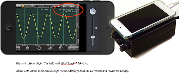
I decided that I didn’t necessarily need to be able to hang the iAudioInterface2 (iAI2) across the largest available amplifiers. I have another meter in the kit that can do that. But, I do want to know if I can safely hang the iAI2 across the output of an amplifier driving a transformer distribution system. A 70.7 Vrms loudspeaker line is about 39 dBu (sine wave). The peak voltage is +3 dB re. 70 V, or about 100 Vpk. The iAI2 claims to handle +40 dBu, but doesn’t provide any details. Since the AudioToolsTM software includes an oscilloscope, I can use the interface to test itself. I bridged the iAudioInterface2 across the output of a large-ish power amplifier, along with the Audio Precision, and drove the amplifier with a 1 kHz sine wave. I then slowly raised the voltage while watching the oscilloscope on the iPod TouchTM. If I could hit 70 Vrms on the voltmeter, and still see a clean sine wave on in AudioTools, then I know that it can handle 100 Vpk, and can safely be connected across a 70 V line. The iAI2 clips at about 152 Vpk on the high range setting, and the measured Vrms matched the reading on the AP. Kudos to Studio Six Digital for designing the iAI2 to allow such a high input voltage. pb
Download a PDF of this article.


