Fine Points of Aiming One-Box Line Arrays III
by Richard Honeycutt
In my first blog in this series, I described the vertical coverage of a line array thus:
- “The vertical coverage can be visualized as the length (height, given the usual mounting orientation) of the array, projected onto the audience plane. Thus an 8′ array will “illuminate” an 8′-high strip of the back wall in an empty auditorium with no seats. The vertical coverage angle thus varies with distance from the array: it can be fairly large if calculated for a point close to the array, and only a few degrees at locations far away. This behavior occurs at frequencies at which the wavelength is less than or equal to the length of the array — a little below 150 Hz for an 8′ array. This same behavior applies for each beam in a multibeam steerable array.”
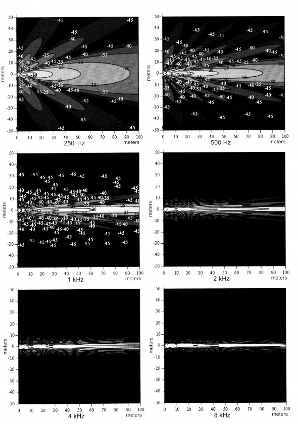
In a comment posted to the SAC site, Dale Shirk pointed out that this description is an oversimplification. As a result, I did some research, not having made definitive measurements of line arrays’ direct coverage. First, I did a CATT simulation using a very tall room (100′) with an SLS LS8695 array mounted horizontally above the center of the room at various heights. Since this speaker is 55″ long, I looked at the direct sound at 1 kHz. Rather than narrowing as the distance from the array was changed from 20′ to 50′ to 100′, as the blog comment suggested, the vertical coverage actually widened. So I cobbled up a 6-element array in Akabak, and looked at 1 kHz at the same three distances, with the same results. After consulting with some folks more knowledgeable than myself, I dug into my JAES archives and found a paper by Mark Ureda (JBL) that included a very enlightening figure, which is included below as Figure 1. (This figure appeared as Figure 13 in “Analysis of Loudspeaker Line Arrays” by Mark S. Ureda of JBL Professional in the May, 2004, issue of JAES, page 475; and is used by permission.)
Remembering that this figure was developed for a 4-m-long array, and that directional radiation is dependent upon the relationship of wavelength and physical dimensions, to apply these results to the LS8695, we would have to multiply frequencies (i.e., divide wavelengths) by (4m/55″)=2.86. Thus the plots would represent 715, 1430, 2860, 5720, 11440, and 22880 Hz, respectively. This vindicated my CATT and Akabak analyses, as in fact the vertical beam does expand with distance in the first two plots, which bracket my 1 kHz analysis frequency. When I re-ran the CATT and Akabak analyses at 8 and 16 kHz, corresponding to Ureda’s last three plots, the results agreed with Ureda’s.
Note that the amount of beam narrowing that actually occurs even at 100 m (328′) is fairly small, and at distances commonly encountered in rooms using single-box line arrays (the topic of these blogs), beam narrowing is negligible. However, beam widening is significant at frequencies that we may habitually consider to be well-controlled by the line array; in the case of the LS8695, anything below 3 kHz is subject to beam widening. The verdict, then, is that I did oversimplify in my description of vertical coverage, but my main point still stands: the vertical coverage of a line array cannot be adequately specified by an angle (or even an angle for each 1/3-octave band). However, my oversimplification is a useful approximation at high enough frequencies for the distances normally encountered in the use of single-box line arrays. “High enough” ranges from about 4 kHz and above for a 1-m-long array to about 1 kHz for a 4-m-long array.
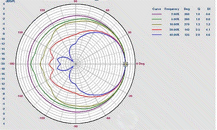
Ureda’s work assumed a true line source. Another issue arises with discrete-element arrays: source directivity. Any driver that is used as a line-array element will have a directivity of its own, as shown in Figure 2. As a result, a listener will be off-axis (meaning less direct field) for elements near the ends of the array, and the effect will become more pronounced at higher frequencies. Thus the effective length of the array decreases as frequency increases. This effect depends upon the directivities of the individual array elements, and may not be properly accounted for in proprietary aiming software provided by manufacturers.
In summary, the directional behavior of a line array can be described in four frequency ranges: the range in which it is omnidirectional, the range in which it is slightly directional, the range in which it acts as a cylindrical radiator with a wedge-like directivity, and the range in which the vertical pattern narrows until the far-field limit of almost a horizontal-line pattern is reached.
Having laid that question to rest, we must now plan on a fourth installment in this series in order to cover the remaining topics. So, until next time . . . .
 Richard A. Honeycutt developed an interest in acoustics and electronics while in elementary school. He assisted with film projection, PA system operation, and audio recording throughout middle and high school. He has been an active holder of the First Class Commercial FCC Radiotelephone license since 1969, and graduated with a BS in Physics from Wake Forest University in 1970, after serving as Student Engineer and Student Station Manager at 50-kW WFDD-FM. His career includes writing engineering and maintenance documents for the Bell Telephone System, operating a loudspeaker manufacture company, teaching Electronics Engineering Technology at the college level, designing and installing audio and video systems, and consulting in acoustics and audio/video design. He earned his Ph.D. in Electroacoustics from the Union Institute in 2004. He is known worldwide as a writer on electronics, acoustics, and philosophy. His two most recent books are Acoustics in Performance and The State of Hollow-State Audio, both published by Elektor.


