Loudspeaker Maximums Part 1 – Continuous SPL
Have you ever tried to find a loudspeaker’s “maximums?” Here’s how you do it.
by Pat Brown
How does one know when a loudspeaker is “all the way up?” There’s some science behind it.
Whether we are selecting an amplifier or setting limiters, the maximum peak and RMS voltages for a loudspeaker are of great interest. These are essentially unrelated, and they must be measured independently. These may be determined by the manufacturer, a third-party test lab, or in the field. While I have written about both in the past, there have been some new developments. It’s time for an in-depth refresh.
These tests can be performed in the field. You don’t need an anechoic chamber – just the great outdoors and some basic instrumentation. You’ll need a USB audio interface. The most important component, the software, is free. Now I have your attention.
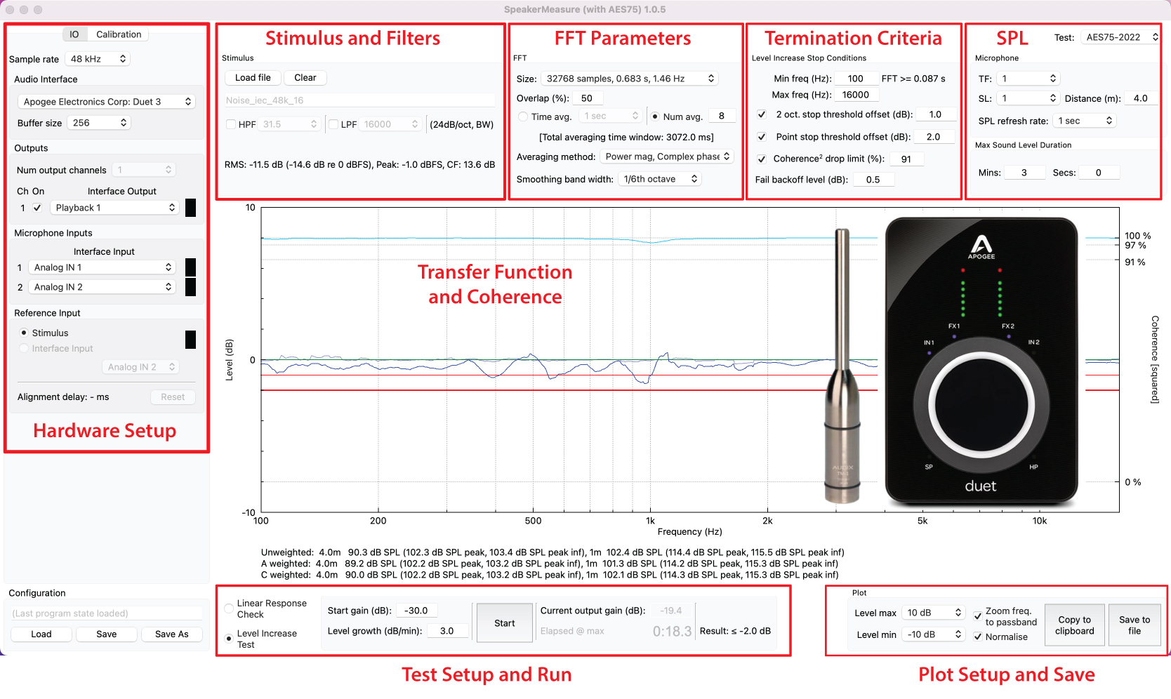
Figure 1 – SpeakerMeasure™ runs on Mac or PC. Just add and audio interface and microphone. I’ve annotated the main sections in red.
Loudspeaker Maximums
There are two “maximums” that guide how we power loudspeakers. Both are determined by the loudspeaker’s physical limitations. The “loudspeaker” may be a single driver or a multi-way system, and either externally or internally powered.
The first maximum is a thermal limit. The second is an excursion limit. Both are associated with the drive voltage from the amplifier, and both can be determined by analyzing the loudspeaker’s response to the drive voltage.
This article describes how to find the loudspeaker’s thermal limit. There are three reasons.
1. Power rating determination
2. Amplifier selection
3. RMS limiter setting
I’ll describe how to find the peak SPL limit in Part 2.
Loudspeakers Get Hot
Current flow from the amplifier produces heat in the loudspeaker’s voice coil and supporting structure. The heat builds over time as the loudspeaker is energized by the amplifier. If the temperature gets too high it causes an increase in the loudspeaker’s electrical impedance, which reduces the current draw from the amplifier. The result is our old nemesis – power compression. With the onset of power compression, the sound pressure level (SPL) from the loudspeaker no longer predictably tracks the applied voltage. With a fixed impedance load, as goes the voltage, so goes the current. This means that we can monitor the voltage (easily done) to see what’s going on.
The maximum RMS input voltage (MIV) for a specified time duration can be determined by measurement and used to rate the loudspeaker, select an amplifier, or to set an RMS limiter.
Finding the Maximum Input Voltage (MIV)
Loudspeakers tend to remain linear in their frequency response vs. drive voltage until their thermal limit is reached. We need a tool for observing how the response changes as the signal level is increased. Ideally it shouldn’t change at all, but at some point, it will. Enter the real-time transfer function. I described how to do this back in the 2000’s with the Loudspeaker Toaster test. The test is still the same in principle, but we now have purpose-built software that formalizes the process and the test termination criteria. Things just got a lot easier.
SpeakerMeasure™ is a free software from Eclipse Audio. I’ll refer to it as SM from here forward. It was released in conjunction with AES75 – Measuring loudspeaker maximum linear sound levels using noise. It is important to note that SM can be used independently of AES75 by checking “Enable advanced AES75-2022 settings” under Preferences.
There is a step-by-step tutorial for SM here. I won’t repeat it, but I’ll add some nuances and additional considerations regarding the setup required for meaningful measurements.
When Noise is Good
A noise waveform is required. There are multiple choices, each sculpted to emulate audio program with a continuous noise signal that can be accurately measured. There are two attributes of interest.
1. The noise spectrum – The spectrum is the “frequency content” of a signal. The spectrum shape of the noise should emulate the program material that will be played over the loudspeaker. Noise types typically originate from technical organizations and bear their initials. Choices include IEC, EIA, CTA, M-Noise, and others. These are all shaped pink noise signals.
2. Figure 2 shows a comparison of spectrum shapes. Figure 3 shows the filter shapes needed to turn pink noise into “whatever” noise. It’s also the spectrum shape that would be observed on a fractional-octave banded analyzer, where the noise is divided and summed into frequency bins (e.g. 30 bands). Figure 2 shows why pink noise is sometimes portrayed as “flat” even though it isn’t (see Figure 1).
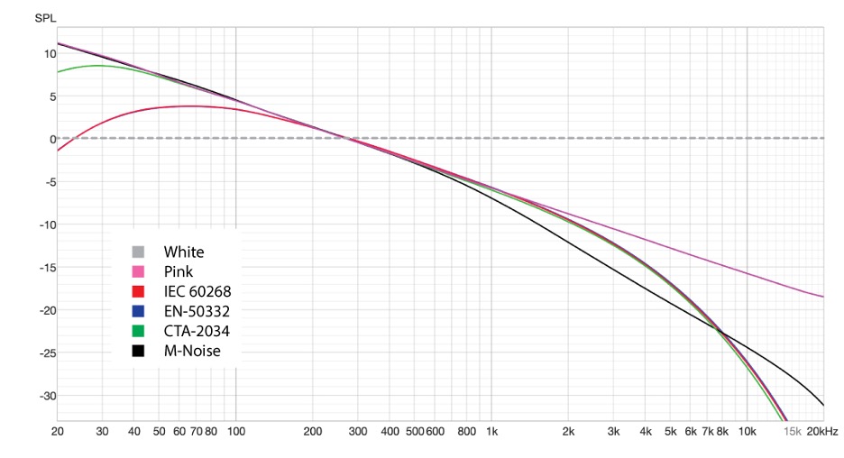
Figure 2 – The overlaid spectra of various noise types.
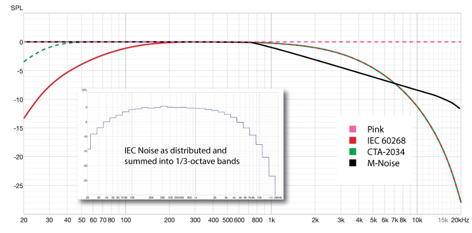
Figure 3 – The filter shapes used to produce the noise types in Figure 2 when applied to pink noise. These curves are also what the noise spectra would look like if summed into fractional octave bins (inset).
3. The noise crest factor – The noise crest factor (peak-to-RMS ratio) is of interest. It is important that the noise spectrum does not change during the test. This can happen if the waveform is clipped as the level is increased. A high crest factor noise signal is unsuitable for a thermal test because unless a massive amplifier is used it may cause amplifier clipping prior to reaching the loudspeaker’s thermal maximum.
The crest factors of three noise types are shown in Figure 4. Of these, BS EN 50332 noise has the lowest crest factor (highest RMS voltage). It was developed for headphone testing but works great for loudspeakers of any type. It allows the MIV test to be run with the smallest amplifier. Yes, it is heavily clipped and sounds terrible, but this is a thermal test, not a sound quality test. We need to find the loudspeaker’s thermal limit before the onset of amplifier clipping.
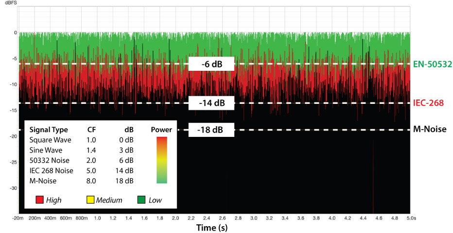
Figure 4– Crest factor comparison of various noise types. High crest factor signals generate low power. Crest factor reduction may be necessary for thermal testing.
Band-Limiting
In addition to the shaping the noise signal should be band-limited for two reasons.
1. A driver can be thermally damaged by program material that is beyond the range of human hearing (too high in frequency).
2. A driver can be mechanically damaged by frequencies below its useful operating range. This is because the excursion quadruples for each halving of frequency.
This is why IEC 60268 noise exhibits a “haystack” frequency response, tapering the frequency extremes to avoid these problems. This also emulates the spectrum of musical program material. Even with the tapering, it may be necessary to feed the noise through a high pass and low pass filter to protect the driver, such as with speech-range devices that will be high-passed when deployed. Without the high pass filter, the DUT’s low frequency excursion limit may be reached before its thermal limit. The resultant distortion can cause the test’s termination criteria to be reached prematurely, and even damage the loudspeaker. SM provides these filters on-board, greatly simplifying the measurement setup.
Start with IEC 60268 noise. If you hit amplifier clipping before the onset of power compression, switch to EN 50332 noise. This will yield a higher RMS voltage from the amplifier without changing the noise spectrum. If you need more low frequency energy, CTA-2034 noise has the same mid/high-frequency spectrum as IEC 60268 noise but with extended low frequency output. Subwoofers can be tested using band-limited pink noise.
There’s no “correct” noise type. Pick the one that is appropriate for what you are testing. It should have a spectrum that covers the loudspeaker’s bandwidth and a crest factor that avoids amplifier clipping.
Mic-to-Loudspeaker Distance
We need the SPL at one meter, without placing the microphone at one meter. Why? The SPL must be monitored in the loudspeaker’s far field – the distance at which the wavefronts become spherical. The waves must be spherical to calculate the SPL further from (and closer) the loudspeaker using the inverse-square law.
How far is that? A generally adequate working guideline is at least 3x the box’s longest dimension perpendicular to the microphone (Figure 5A). Typical measurement distances are 2, 4, 6, and 8 m. The closer you get, the greater the danger of over-driving your measurement microphone. The farther you get, the greater the danger of violating the free field criteria (no reflections) and being plagued by wind effects, etc.
Enter the selected distance in SM. The measured level is corrected to 1 m during the test by SM using the inverse-square law.
Component Placement
There are three choices for the component placements. All three require free field conditions. “Free field” means “no reflections.” Please refer to Figure 5.
A. Both microphone and loudspeaker in a free field.
B. The loudspeaker flown with the mic on a ground plane (large, ridged boundary).
C. Both loudspeaker and mic on a ground plane.
All three are essentially identical regarding the loudspeaker’s response. Two and three require that the measured level be reduced by 6 dB since placing the microphone on a boundary increases its sensitivity by 6 dB. This can be accomplished by modifying the calibration settings in SM.
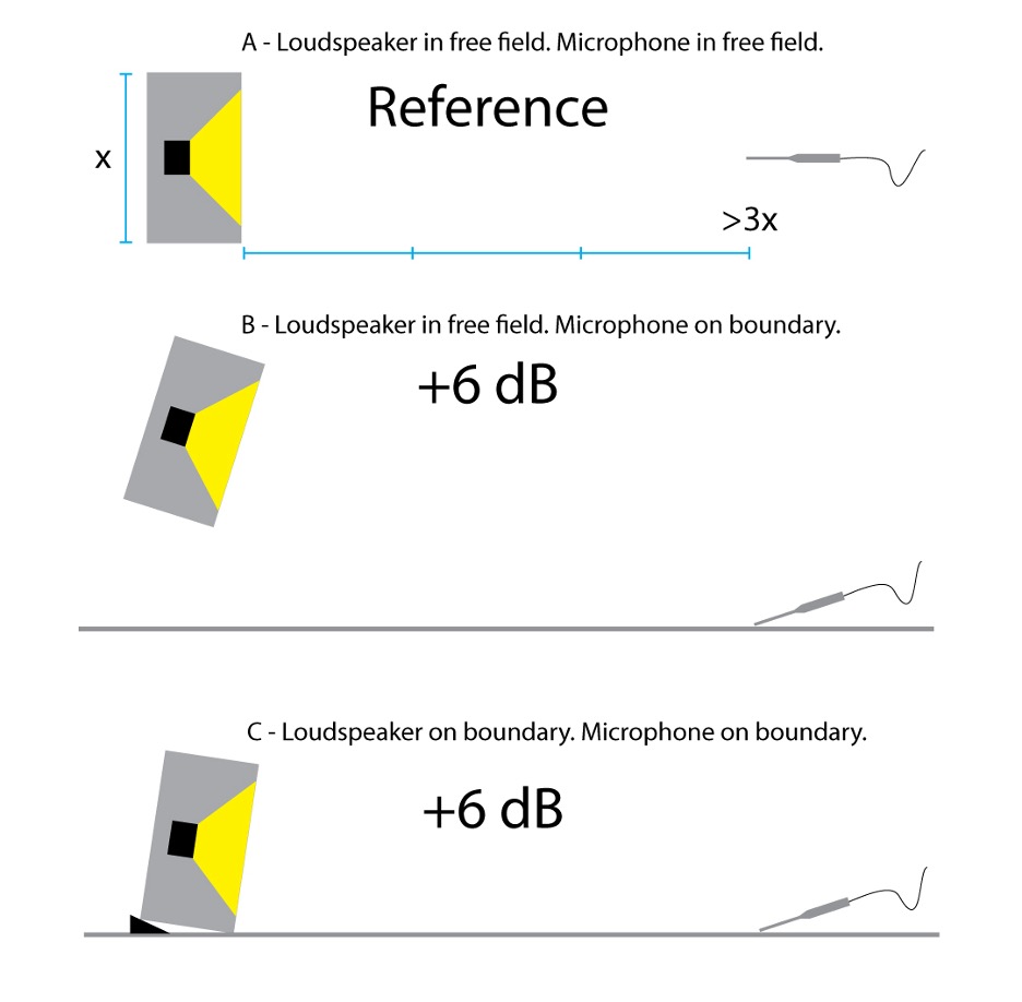
Figure 5 – Loudspeaker/microphone placements for MIV testing.
Indoors or Outdoors?
This is one test that can effectively be performed outdoors. This removes the room gain caused by reflections indoors, fulfilling the free field requirement. You can move things indoors if you have an extremely large space, but most of us don’t. It helps to have a calm day without temperature extremes.
The Weakest Link
Figure 5 shows the measurement signal chain. It is very important that we reach the loudspeaker’s MIV before clipping occurs in any of the upstream components. Most measurement microphones can handle 130 – 140 dBSPL before they clip. If you stage this test properly that should be enough. Figure 6 shows the metrics for an Audix TM1™ measurement microphone. With the microphone at 4 m, the max level that can be measured is about 142 dBSPL. The figure also shows how much additional level can be handled if the microphone is moved to a greater distance. Remember that a boundary placement increases the level at the mic by 6 dB.
A secondary concern is that the microphone output signal overdrives the mic preamp. Figure 5 shows how to calculate the microphone output level (or preamp input level). Most mic preamps can handle 0 dBV or more, so no real concern here. (Hint: if the measured TF drops quickly and uniformly with frequency, you’re probably clipping the microphone or the mic pre. Loudspeaker power compression comes on gradually and is frequency-dependent).
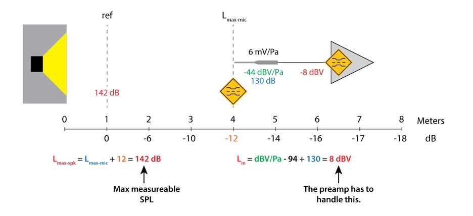
Figure 6 – The potential “choke” points in the signal chain are the microphone (acoustic) and preamp (electrical) inputs.
The Voltmeter
The voltage applied to the DUT must be monitored during the test. This can be accomplished with a True RMS voltmeter. I prefer to track the voltage over time, as this allows the onset of the termination criteria to be clearly observed. Figure 7 shows the MIV test signal monitored using the CLIO 12 measurement platform. It provides a time record of the entire test. Note the level changes automatically performed by SM when the termination criteria are reached. Per AES75, SM’s default termination criteria (TC) are
1. Any part of the transfer function hits the -3 dB line.
2. A two-octave wide segment of the TF hits the -2 dB line.
3. The coherence falls below 91%.
When one of these criteria are met, SM applies a backoff level to reduce the drive signal level, 0.5 dB by default. Once below the termination criteria, a timer starts to show how long the loudspeaker has remained stable.
Monitoring the SPL
The loudspeaker’s sound pressure level can and should be monitored during the test. This can also be handled by SM. You’ll need a calibrator for your measurement microphone. If you don’t have one, you should have. The calibration process tells SM (or any measurement interface) the number of millivolts your microphone produces when exposed to 94 dBSPL and/or 114 dBSPL. I’d use the 114 dB setting if available since it is closer to the expected (high) SPL.
This is important. You must set the input level on your audio interface before running the calibration in SM. Once you calibrate, you can’t change the setting without ruining your calibration.
To simplify the setup, you can use the same microphone to monitor the transfer function and measure the SPL.
Now, the Test
The test begins with a noise voltage applied to the loudspeaker that is at least -20 dB re. the expected MIV. The voltage is slowly increased (1-3 dB/min recommended) until one of the termination criteria are met. When this happens SM backs the voltage down by 0.5 dB and a timer counts how long the voltage remains constant (the system remains stable). This Max Sound Level Duration defaults to 5 min – a defensible value. I used 3 min for the test shown in Figure 7. If during the duration test the termination criteria are again met, the process is repeated.
The difference between the starting transfer function and the current transfer function is displayed in real-time (Figure 8). This allows one to observe the response change as the TC are approached. They can also see the nature of the change (broadband, narrowband, etc.).
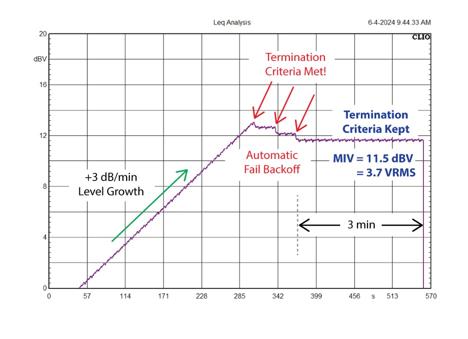 Figure 7 – The applied voltage as tracked by a CLIO 12 measurement system. I have annotated some significant events in the time record. This test is for a small, cone loudspeaker, but it could just as easily have been for a large, internally powered line array box. Either way, the MIV is a voltage.
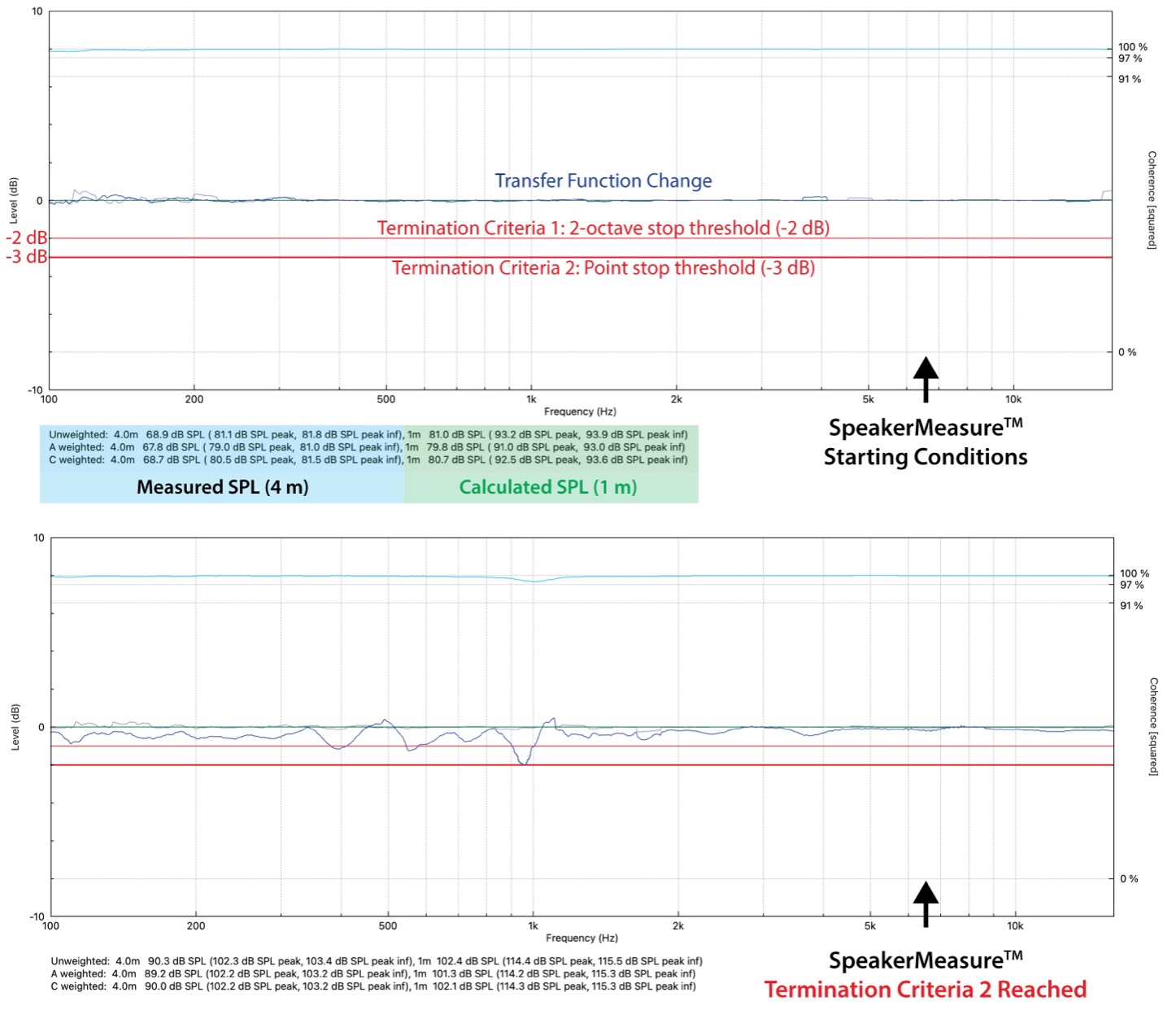
Figure 8 – SpeakerMeasure monitors the change to the transfer function as the applied voltage to the loudspeaker is increased. It keeps the TF change just below the termination criteria threshold for 3 min. The SPL is monitored and indicated.
Summary
The thermal limits of a loudspeaker can be accurately determined by measurement. The test requires a real-time transfer function. In the past I have used ARTA, CLIO, and others. SpeakerMeasure™ simplifies the measurement setup and automates the process, making the execution of the MIV test more accessible to all.
As with all instrumentation tasks, lock yourself in a room and run the test on as many devices as you can. With repetition the process becomes more logical and you will develop your intuition regarding the results. Start off with test subjects that are expendable. Things can happen, but don’t let them happen to your good stuff. pb
Be sure to check out Loudspeaker Maximums – Part 2 – Peak SPL.
“If you’re not experiencing failures you’re not trying anything. If you’re not trying anything, you’re not learning anything.” Anonymous

