The Effect of Mounting on Absorption
It’s not just what you put on the wall or ceiling. The mounting method matters.
by Richard Honeycutt
As you probably know, acoustical absorption includes several elements: wall, floor, and ceiling materials, occupants, and openings to the outdoors or to other large spaces. Often, we need to add specific acoustical absorbing materials such as carpet, wall panels, absorptive ceiling tiles, etc.
Carpets tend to be over-rated as acoustical absorbers. Figure 1 shows the Sabine absorption plotted versus frequency for various carpets with and without underpads, on different substrates.
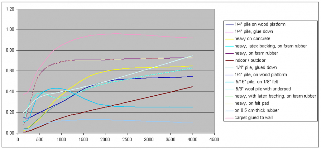
Figure 1: The Sabine absorption coefficient for various carpets plotted vs. octave-band center frequency.
As you can see, carpet has poor absorption at frequencies where most of the sound power from speech and music exists. Sometimes, the judicious use of carpeting can improve speech intelligibility in classrooms or conference rooms, but carpeting tends to make auditoria sound dull.
Ceiling tiles have long been used for acoustical absorption. Beginning in the mid Twentieth Century or earlier, staple-up mineral fiber tiles were commonly used for both new construction and renovation. By the mid-1970s, the popularity of these gave way to “popcorn-finished” gypsum board. The absorption performance of these materials is shown in Figure 2.
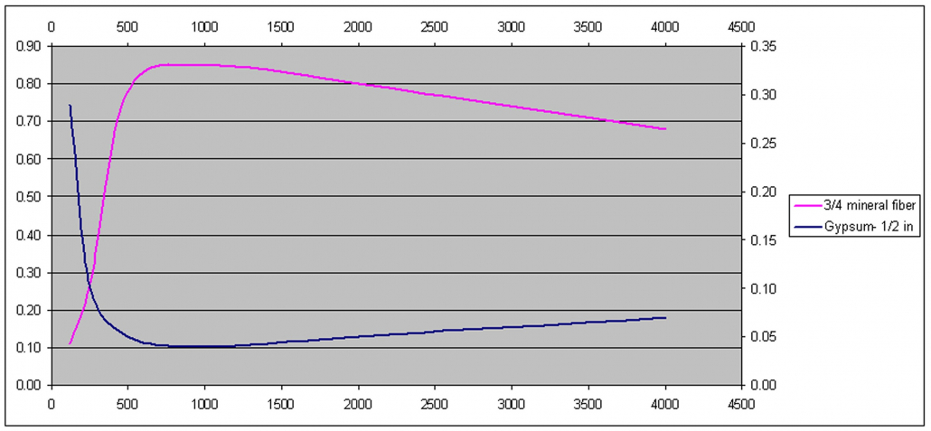
Figure 2: The Sabine absorption coefficient for glued or stapled ceilings vs. octave-band center frequency.
While stapled or glued mineral fiber tiles do provide significant absorption at higher frequencies, they—like carpeting—have little benefit in the critical 500 Hz octave band and below. The significant absorption of the gypsum at low frequencies results from diaphragmatic action of the gypsum itself, plus the material (usually thin wood) to which it is affixed. Mounting an absorptive material directly to a rigid substrate is called A Mounting, or if the absorption is glued to the substrate, B Mounting.
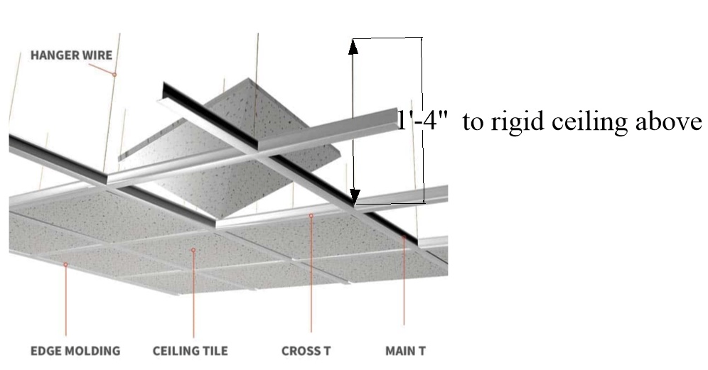
Acoustically absorptive wall and ceiling panels can be mounted in a variety of ways. Mineral fiber or fiberglass ceiling tiles are often mounted in suspended grids with an airspace between the tiles and a rigid ceiling above. (See Figure 3.) This is called E-XXX Mounting. The XXX is a three-digit number denoting the height of the airspace in millimeters. The most common variant is E-400 Mounting. (400 mm is about 16″.)
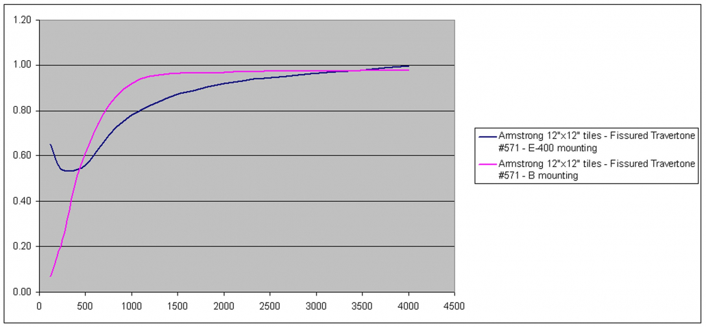
Figure 4 shows the Sabine absorption coefficient of Armstrong Fissured Travertone™ mineral fiber ceiling tiles with an E-400 Mounting versus a B Mounting. Note the significant increase in low-frequency absorption at low frequencies with the E-400 Mounting.
The approximate physics behind the increased LF absorption for E-400-mounted tiles is that the direct sound striking the bottom of the tile is antiphase to the wave reflected from the rigid ceiling when the total path length (= twice the spacing if the tile from the ceiling) is an odd number of half-wavelengths of the sound. This causes constructive interference of the sound—maximum particle velocity—in the plane of the panel. Since absorption in porous materials depends upon particle velocity, absorption is maximized at these frequencies. This condition occurs when the spacing is an odd number of quarter wavelengths. This explanation ignores the thickness of the tiles and the slight change in sound velocity occurring when the sound enters the tile. So to be precise, although 16″=λ /4 at a frequency of 211 Hz in air, the actual peak in absorption of an E-400-Mounted mineral fiber tile is closer to 125 Hz.
When sound-absorptive wall panels are used, the installer has a number of mounting options: A, B, and several versions of C and D. As shown in Figure 5, D Mounting involves furring the panel out from the rigid wall on which it is mounted, creating an airspace. This causes the higher-particle-velocity part of the sound wave to interact more fully with the absorptive material. (Remember that the point at which the wave strikes the rigid wall is forced to zero particle velocity, since air molecules cannot enter the rigid substrate. C Mounting is similar, but with low-density fiberglass in the cavity.
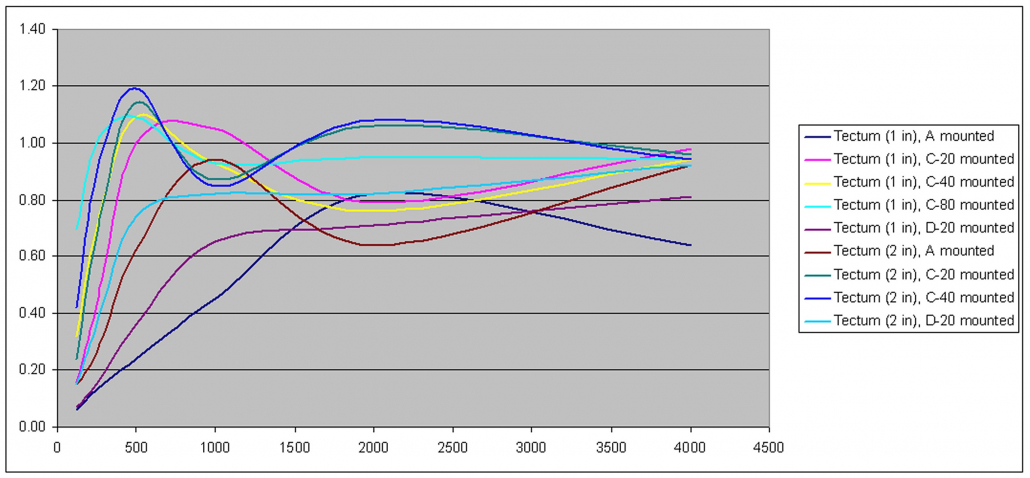
As with E Mounting, C and D Mountings have numerical suffixes indicating the spacing (in millimeters) of the panel from the rigid substrate. The most common ones are D-20, D-40, C-20, C-40, and C-80, corresponding to furring strips having thicknesses of about 3/4″, 1 1/2″, and 3”, respectively. Often so-called 2×2’s are used to approximate the 40 mm spacing, and 2×4s mounted on edge for the 80 mm spacing. Examples of the Sabine absorption coefficient Tectum wall panels with several different mountings are shown in Figure 6.
Note that in some cases—such as 1” C-40 and 2” C-20—panel thickness and mounting type can be traded off while equivalent performance is maintained. Such choices may become the job of the architect, as costs can be affected.
I have consulted on several projects in which good low-frequency absorption was achieved by using 1” Tectum™ panels (https://www.armstrongceilings.com/commercial/en/commercial-ceilings-walls/tectum-direct-attach-wall-panels.html) instead of gypsum on the inside face of an auditorium wall, effectively creating aa C-80 mounting without the need for furring strips. Building insulation batts are placed in the cavity behind the Tectum. rh

