Small Format Line Arrays
by Pat Brown
A small format line array in its simplest form is a number of transducers (usually cones) arranged in a tight-packed vertical line. The line length is typically about 1 meter or less. For years such arrays were known as “sound columns” and you either loved or hated them, depending on the application. I’ll refer to them as a sound columns in this blog because it’s easier to type than “small format line array” and it distinguishes them from other array types.
Another entry into the small format line array market is the CBT array.
CBT is an acronym for Constant Beamwidth Transducer. A CBT array looks like a sound column. It is claimed to have constant beamwidth and no near field, which would be quite unusual for a loudspeaker of this form factor.
If you are new to loudspeakers you should view Loudspeaker Fundamentals Parts 1 and 2 of our Level 100 Online training for a primer on the theory and terms needed to understand loudspeaker behavior.
Some Background
Sound columns have been around nearly as long as the cone loudspeakers used to create them. I’ve covered their performance characteristics in previous articles. Here’s one that describes their typical behavior.
The CBT array was invented by Don Keele while working for JBL. His website is a wealth of CBT (and other) information. Don has many other acoustic inventions to his credit, include the constant directivity horn. Note that CBT arrays can be curved or straight. The compact commercial versions sold by JBL are straight, using passive filtering to achieve the needed weightings between the transducers.
I have not previously measured a CBT array, so to verify the claims I measured a JBL CBT100. I’ll consider the attributes of constant beamwidth and no near field independently.
Constant Beamwidth
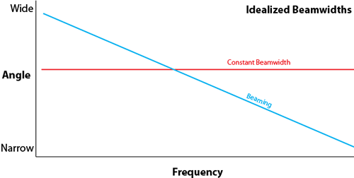
A loudspeaker with constant beamwidth has a coverage pattern that is independent of frequency. For example, all octave bands would cover 40, 60 or whatever degrees. A plot of coverage angle vs. frequency would be a straight horizontal line.
Contrast this with the same plot for a cone loudspeaker (or sound column), where the line would have a downward slope from low frequency to high frequency. The high frequency coverage angle would be quite narrow, a phenomenon known as “beaming.”
The graphic shows the idealized beamwidth of these two behaviors.
Near Field
In the far field, the sound from the loudspeaker expands spherically as it propagates. Imagine a multi-colored ball, where the colors indicate the intensity of sound. The ball grows as it is inflated with air.
In the near field, the colors would shift around as the ball grows, finally stabilizing when the far field is reached. Virtually all loudspeakers (especially sound columns) have a near field that extends to a distance that is large relative to the largest dimension of the loudspeaker (3 to 10 times, depending on why you need to know).
In the near field, the frequency response and polar pattern change with distance. Measure the response at one meter, and you will get a different one at 2 meters. If you keep increasing the distance, the response becomes repeatable, other than dropping in level at -6 dB per distance double. Of course there is also some air absorption losses that are most pronounced at high frequencies.
Sound Column Data
The article referenced earlier shows the frequency response of a sound column as a function of distance. It flattens out as distance is increased, eventually looking like what you see on the spec sheet.
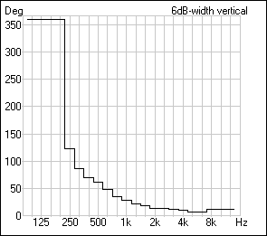
The figure below shows the vertical coverage angle of a sound column as a function of frequency, measured in the far field of this array. Note that the coverage narrows as frequency increases. So, the measured data shows that this device has a near field, and is not constant beamwidth. I’m not saying that’s bad, but it is what it is. Don’t skip my conclusions at the end of this blog.
CBT Array Data
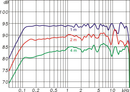
I tested a CBT array of approximately the same height at 1 m, 2m and 4 m. The plot shows the overlaid frequency response magnitudes. Note that the response is essentially independent of distance, other than the level change. This indeed suggests that the loudspeaker has no near field. The response is equalized, and the equalizer curve is valid at any distance, something that is not true for a loudspeaker with a near field.
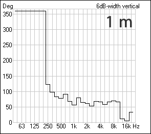
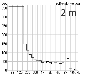
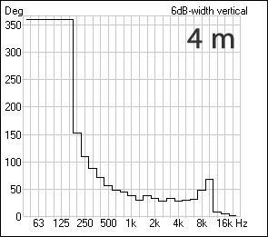
I then measured a vertical polar at the same distances, and from it determined the beamwidth (the -6 dB points on the polar). The figure shows the result as displayed in the CLF Viewer. The device is indeed constant beamwidth over nearly all of its useful bandwidth. The coverage narrows slightly as distance increases, but I would not expect much additional change beyond my 4 m maximum distance.
The CBT array delivers on both claims, constant beamwidth and no (or at least a very short) near field.
Conclusions
Is a CBT array better than a conventional small format line array? You know the answer- it depends!
The collapsing vertical pattern of the sound column can be very useful in keeping sound energy off the room and on the listeners. The far field response still has this collapsed pattern (even though it grows spherically with increasing distance) and this attribute can give the array significant “reach” to remote listeners. Since it has a near field, up close listeners will hear a different frequency response than remote listeners. That may not matter since you can’t be in both places at once. The objective is to produce good intelligibility (or music clarity) to all listeners, and the back rows need more “umph” than the front rows. Such arrays can also be stacked to increase their working distance.
The CBT array may be preferred for applications where a wider vertical pattern is needed, and where listeners will sit very near the loudspeaker. I can think of many applications where that would be useful, such as evenly covering a sloped seating area. The loudspeaker could also be rotated 90 degrees and still have a useful coverage angle. This would make it nice for snugging up under a balcony or zoning the coverage of several arrays down a long wall.
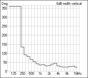
I should also point out that it is not “either/or” when selecting a small format line array. It is also possible to have a vertical pattern that is both narrow and constant beamwidth. The graphic shows the far field vertical coverage for the Frazier CAT 2X7. Sometimes you need a narrow vertical pattern, but not too narrow, such as for an overhead choir monitor. There are trade-offs in this design, too. This loudspeaker has a near field, and less low frequency output than the other array types.
All three array types are tools in the tool bag of the system designer. They are apples, oranges and pears. As with any tool, you grab the one you need for what you are doing. When comparing array types we should avoid the terms “better” or “worse” and substitute “appropriate.” Use the published data to pre-qualify the array for a design. Only a listening test conducted IN THE VENUE can account for all of the variables.
Don’t assume that all small format line arrays behave the same. Take the time to consider what you need for the application. When laying out the coverage at the drawing board, moving the array from ear height to overhead may require a switch to a different type of small format line array. pb

