Single-Source Solutions for Meeting Rooms
Practical Audio Solutions – By Pat Brown
Simple mechanical aiming and active beam-steering provide single-source solutions for small spaces.
A common application of both fixed and portable sound reinforcement systems is for meetings spaces of 50 people or less seated on a flat floor plane. Most SynAudCon seminars fall into this category, and I have had many opportunities to experiment with various approaches for covering such spaces. Here are some approaches that have produced good results.
Aiming
One of the important principles to follow in such spaces is to aim the loudspeaker at the back row. Those folks need the highest SPL and directivity, both of which are usually on the main axis of the loudspeaker. It is also important to not overpower the front rows when projecting sound to the back rows. This mandates a tight vertical coverage pattern – one that can miss the front when aimed at the back. Elevating the loudspeaker helps tremendously in achieving even coverage, but meeting rooms generally have ceiling height restrictions that limit how high the loudspeaker can go.
Line Array
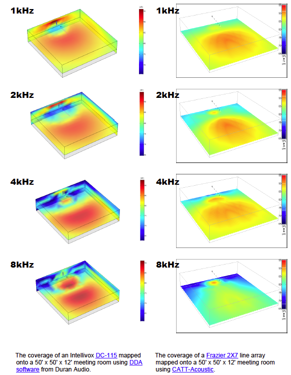
Since so many of our seminars are held in rooms that are approximately 50 ft x 50 ft x 12 ft I modeled the room and tried a few loudspeaker balloons for coverage.
It is immediately apparent that a low loudspeaker placement requires vertical pattern control. The small-format line array (or sound column) is well-suited for this task. The horizontal pattern is typically broad due to the use of small transducers in the array. The vertical pattern is narrowed at high frequencies due to the phase relationships of the vertically-stacked drivers. This “Frisbee-shaped” pattern allows sound energy to be concentrated on the farthest listeners, and fall off in the front of the room where the listeners are closer to the loudspeaker (and talker).
.
Placement

I made an angled pole cup by chopsawing a straight one and welding it back. Be sure that the ldspk center-of-gravity is correctly positioned!
One often hears that the loudspeaker should never be placed behind the talker. On the contrary, this is an excellent placement, as it allows natural acoustical imaging for nearly all of the audience. On many occasions I have heard Don Davis proclaim that “Microphones don’t have eyes, they only have ears!” This means that the only thing that matters are the relative sound levels presented to the mic by the talker and loudspeaker. So long as the talker’s level dominates what the mic “hears” the system will be stable. There are two ways to assure that this happens:
1. Utilize the loudspeaker’s radiation pattern to reduce the sound energy at the microphone, and
2. Reduce the mic-to-source distance until the talker’s level dominates.
I maximize both principles by using an elevated line array and headworn mic. This combination produces excellent acoustic gain. Another benefit is the
natural acoustic image experienced by the audience – the sound is coming from where the lips are moving. Since the array-to-audience distance is longer than the talker-to-audience distance, a nice precedence effect is also achieved.
The Whole Package
While the afore-mentioned principles can produce excellent results, one can make things even better with a few simple embellishments to the process.
Elevating the loudspeaker provides some increased isolation from the microphone pattern. Tripod stands that raise it to 10-12 ft are readily available. Elevating the loudspeaker also necessitates some downward tilt. An active beam-steered line array (i.e. Intellivox) can be positioned perpendicular to the floor and the pattern can be tilted to the desired angle electronically. A passive line array can be tilted mechanically. I achieved this by modifying a metal pole cup to have the 10-degree downward angle that the room modeling program suggested as ideal.
The “Above-Behind-Tilt” method is a simple solution to a common problem.
The benefits include
- Single loudspeaker
- Excellent imaging
- Quick Setup
- Universal Application
The only downside that I can think of is constantly having to explain how it works, and that I am not violating any physical laws by using this method. pb
Hotel Meeting Room
Download impulse responses from an active and a passive line array at three listener positions. A Sketchup room model is included for import into a supporting room modeling program. Use GratisVolver to listen to the test positions with anechoic program material. The CLF data for the passive array is available from www.clfgroup.org. The EASE data for the passive array is available from www.frazierspeakers.com. Hotel Meeting Room…


