
What is the Difference Between Delay, Phase Shift, and Polarity?
by Pat Brown
Wavelets are both a theoretical tool and a system tuning tool. Pat Brown explains how to use them to address some common system tuning problems.
In the time domain, we are blind to frequency. In the frequency domain, we are blind to time (Figure 1). This results from one of the most important relationships in audio:
TF = 1
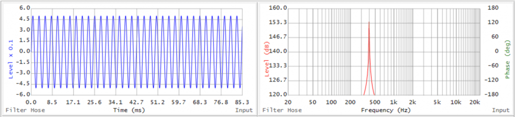
Time and Frequency are defined in terms of each other (Figure 2). The more you know about one the less you know about the other. This is a manifestation of the Heisenberg Uncertainty principle which states that the position and the velocity of an object cannot both be measured exactly, at the same time, even in theory. The more you learn about one, the less you know about the other. Period.
Sine waves are useless for timing chores, and impulses are useless for equalization chores. Our analyzers allow us to jump between these two exclusive views to get the job done, answering two important questions:
- When? (time domain)
- What? (frequency domain)
Time and frequency can be observed simultaneously if we sacrifice information in both domains. Compromise is a critical aspect of audio. It often provides the most beneficial solution.
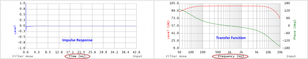
Figure 1 – The IR (left) is frequency blind, and the TF (right) is time blind (courtesy Filter Hose).
Enter the Wavelet
We can clear things up by using a sine wave segment, or wavelet. A wavelet is neither an impulse nor a sine wave. It is a compromise. Figure 3 shows a sine wave of Figure 2 after the application of a symmetrical time window. It now has a beginning and an end. In the time domain, it is now more compacted (an increase in information). In the frequency domain, it now has broader spectral content (a decrease in information). TF = 1 is at work. We have sacrificed information in both domains to have some information about both, and as it turns out this is enough information to accomplish some important system tuning tasks.
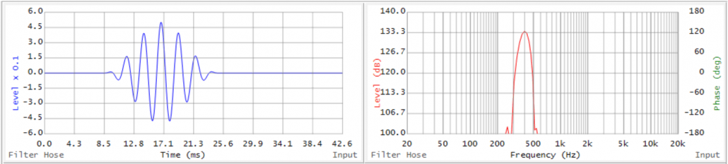
Figure 3 – A wavelet sacrifices resolution in both domains to yield some information about each.
A wavelet with a known center frequency can be injected into a system and its arrival time observed on an oscilloscope. If you don’t have a scope, I’ll show you a better way at the end of this article. Wavelet analysis provides a clear distinction between three quantities that are often mistaken for one another – arrival time, phase shift, and polarity. What is hidden in impulses and sine waves can be revealed using wavelets. The wavelet gives us a way to probe the concept of “frequency arrival time” which is something that TF =1 says that we cannot know.
If the wavelet seems like a highly theoretical and esoteric concept, it isn’t. A kick drum sample is a sort of wavelet. What could be more intuitive than synchronizing systems using percussive sounds, either by listening or by observing them on an instrument? You can think of the wavelet as a well-defined, perfectly repeatable kick drum sample.
When attempting to “align” things in audio and acoustics, wavelets can prove to be very useful. They allow us to distinguish between delay, phase shift, and polarity using an intuitive method that is easier to interpret than an impulse response or a transfer function.
Wavelet Obstacle Course
Figure 4 shows three wavelets. Each is 6.5 cycles of a sine wave that has been windowed to taper the ends. Due to its short duration, its bandwidth is about 1/3-oct due to TF = 1.
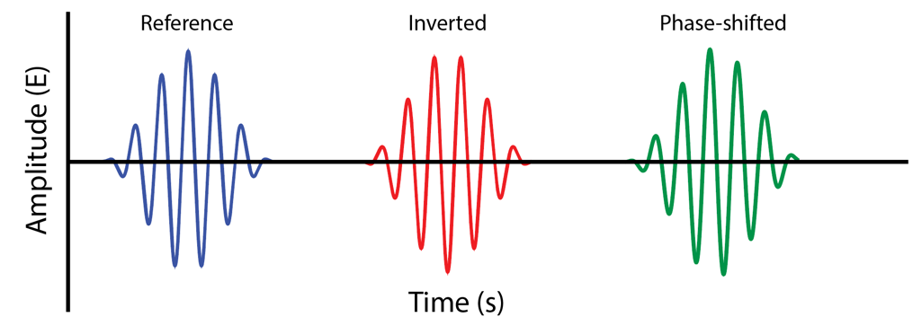
Figure 4 – Some reference wavelets.
The blue wavelet serves as the reference. If the wavelet is passed through a delay, it moves to the right (positive time). There’s no way to move it to the left (negative time). Most importantly, the delay does not introduce phase shift, which means that the wave shape is unaffected.
The red wavelet is delayed relative to the blue wavelet, and inverted in polarity. It is simply flipped over, a condition that results from swapping the two wires that connect to a loudspeaker or swapping the twisted-pair in a balanced interface. The wave shape is not changed by a polarity inversion.
The green wavelet has been passed through an all pass filter (APF). It is delayed relative to the other wavelets, but one can imagine removing the delay to superimpose them. The APF leaves the amplitude unaffected but introduces phase shift. The phase rotation is frequency-dependent, meaning some frequencies are rotating more than others. This makes the wavelet asymmetrical. The wave shape has been changed. This creates an important distinction between a delay and an APF. The APF alters the wave’s shape. Delay does not. Delay slides the wavelet down the time axis. The APF rotates it down the time axis. Think of turning vs. hammering a screw and you have the right mental image.
Examples
I’ll use these three wavelets to produce examples of various synchronicity issues that affect sound systems. The following time domain plots are laid out consecutively to facilitate comparison (Figure 5). I’ve described the relationship in each case in terms of time, phase, and polarity. I have also indicated the tool(s) required to correct the relationship. We have three on our palette: delay (ΔT), all-pass filter (APF), and polarity switch (+/-).
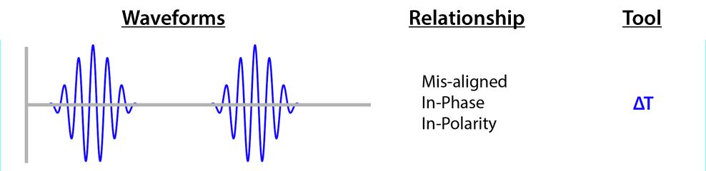
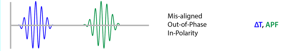
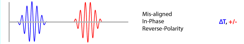


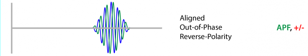

Figure 5 – Wavelet relationships
The Take-Away
If you need to change the position of the wavelet, use a delay. If you need to change the shape of the wavelet, use an APF. If you need to flip the wavelet without changing its shape, use a polarity switch.
For a wavelet, a delay and an APF can appear to do the same thing. One might even say that the APF is functioning as a delay. The ambiguity is removed by passing a broadband signal (e.g. impulse) through each and comparing the results, which are not even remotely similar. The APF changes the wave shape. The delay does not – an important distinction. If you want to slide the wavelet use a delay. If you want to change its shape by rotating it, use an APF. Both may be required to “sync” two signals.
Applications
So, where would wavelet analysis come in handy?
1. Aligning a multiway loudspeaker.
2. Aligning mains with subs.
3. Quickly finding the time offset between any two sources, such as main and under-balcony loudspeakers.
Of course all of these tasks can be accomplished using IRs and TFs, but these are not as intuitive as using wavelets.
Practical Wavelet Measurements
So, how do I add wavelet analysis to my measurement arsenal? A simple way is to just make WAV recordings of wavelets played over the system. The wavelets can be played from your PC or a media player. Wavelets can be generated in some WAV editors (e.g. Goldwave), or obtained from online resources such as Wavtones™.
I have a wavelet library loaded onto my NTI MR-Pro. Here’s a ZIP file with 20 Hz – 20 kHz wavelets spaced at 1/3-octave. You can open and edit them as you please with any WAV editor.

I’ve saved the best until last. The ARTA measurement app (Windows™) can generate and record wavelets. Figure 6 shows the setup dialog. The Transient Generator section can produce a wavelet at a user-selected frequency and number of cycles. This can then be played through the system and recorded. Using the loopback signal as a trigger, accurate delay measurements are possible.
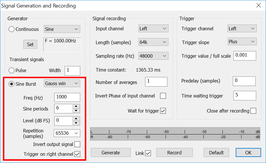
Figure 6 – Sine bursts can be generated and played using ARTA.
One application is investigating the alignment between a full-range loudspeaker and a subwoofer. Assuming you have selected a meaningful test position, proceed as follows:
1. Create a wavelet at the crossover frequency, which by definition is a frequency range shared by both the main loudspeaker and the subwoofer.
2. Play it through the main or the sub. Set this as an “overlay” in ARTA.
3. Repeat the process, this time playing it through the other pass band.
4. The arrival time differential is now displayed.
5. Add delay to the earlier arrival until they are synced. Add an APF if you want to change the wave shape.
6. Alternately you can play the wavelet through both the main and sub and view them in ARTA. Use the tools described above to align them.
Signal delay can be used to fix the timing. An APF can be used to match the wave shape. While there are other ways to get there, this is both fast and intuitive. In my opinion, compensating the arrival time differential is vastly more important than matching the wave shapes. And since the arrival time differential is position-dependent the process must begin at the drawing board. For many systems “sub-alignment” is not a meaningful pursuit.
Conclusion
I love getting new tools, and I love learning more about the existing tools. What I love most is to find out that I already have a tool but just haven’t been using it. Wavelets are “truth tellers” that help us distinguish between three quantities that are different but can masquerade as each other: delay, phase shift, and polarity. Wavelets are both a theoretical and a system tuning tool. They allow us to work with both time and frequency information simultaneously, as a compromise to the impulse response and transfer function.
And sometimes compromise is just what is needed to solve a problem. pb